Plans
The Design & Construction of Vacuum Tube Tesla Coils
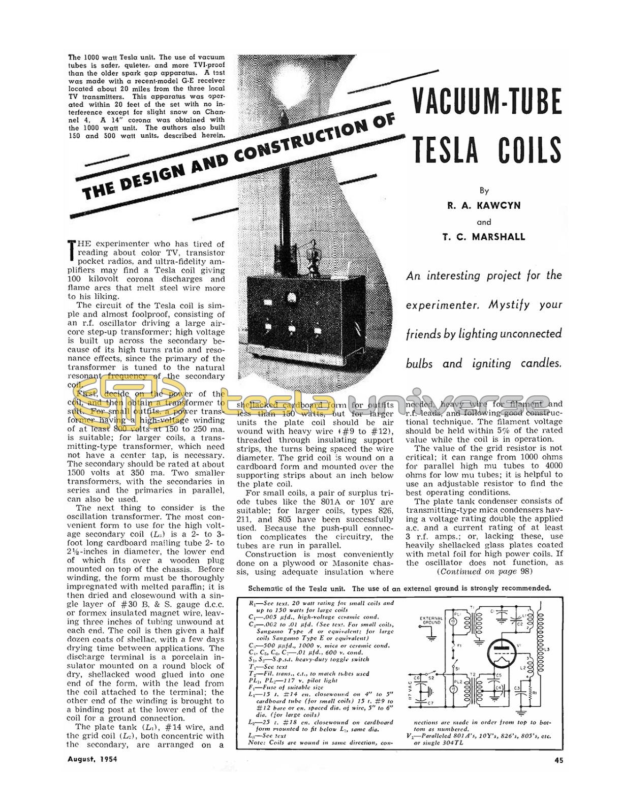
An interesting project for the experimenter. Mystify your friends by lighting unconnected bulbs and igniting candles.
By R. A. KAWCYN and T. C. MARSHALL
The experimenter who has tired of reading about color TV, transistor pocket radios, and ultra-fidelity amplifiers may find a Tesla coil giving 100 kilovolt corona discharges and flame arcs that melt steel wire more to his liking.
The circuit of the Tesla coil is simple and almost foolproof, consisting of an r.f. oscillator driving a large air-core step-up transformer; high voltage is built up across the secondary because of its high turns ratio and resonance effects, since the primary of the transformer is tuned to the natural resonant frequency of the secondary coil.
First, decide on the power of the coil, and then obtain a transformer to suit. For small outfits, a power transformer having a high-voltage winding of at least 800 volts at 150 to 250 mA is suitable; for larger coils, a transmitting-type transformer, which need not have a center tap, is necessary. The secondary should be rated at about 1500 volts at 350 mA. Two smaller transformers, with the secondaries in series and the primaries in parallel, can also be used.
The next thing to consider is the oscillation transformer. The most convenient form to use for the high voltage secondary coil (L₃) is a 2 to 3- foot long cardboard mailing tube 2- to 2 1/2-inches in diameter, the lower end of which fits over a wooden plug mounted on top of the chassis. Before winding, the form must be thoroughly impregnated with melted paraffin; it is then dried and closewound with a single layer of #30 B. & S. gauge d.c.c. or Formex insulated magnet wire, leaving three inches of tubing unwound at each end. The coil is then given a half dozen coats of shellac, with a few days drying time between applications. The discharge terminal is a porcelain insulator mounted on a round block of dry, shellacked wood glued into one end of the form, with the lead from the coil attached to the terminal; the other end of the winding is brought to a binding post at the lower end of the coil for a ground connection.
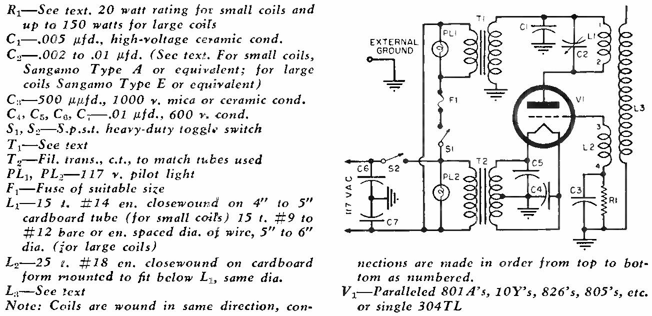
The plate tank (L₁), #14 wire, and the grid coil (L₂), both concentric with the secondary, are arranged on a August, 1954 shellacked cardboard form for outfits less than 150 watts, but for larger units the plate coil should be air wound with heavy wire (#9 to #12), threaded through insulating support strips, the turns being spaced the wire diameter. The grid coil is wound on a cardboard form and mounted over the supporting strips about an inch below the plate coil.
For small coils, a pair of surplus triode tubes like the 801A or 10Y are suitable; for larger coils, types 826, 211, and 805 have been successfully used. Because the push-pull connection complicates the circuitry, the tubes are run in parallel.
Construction is most conveniently done on a plywood or Masonite chassis, using adequate insulation where needed, heavy wire for filament and r.f. leads, and following good constructional technique. The filament voltage should be held within 5% of the rated value while the coil is in operation.
The value of the grid resistor is not critical; it can range from 1000 ohms for parallel high mu tubes to 4000 ohms for low mu tubes; it is helpful to use an adjustable resistor to find the best operating conditions.
The plate tank condenser consists of transmitting-type mica condensers having a voltage rating double the applied a.c. and a current rating of at least 3 r.f. amps.; or, lacking these, use heavily shellacked glass plates coated with metal foil for high power coils. If the oscillator does not function, as shown by the lack of glow in a neon bulb when touched to the tank circuit, try reversing the leads to the grid coil, and then tune the plate circuit by arranging two or three condensers in series and parallel until resonance is reached, when a corona should come from the discharge point. The best output is obtained with the highest value of capacitance that causes reso- nance. With the coils described, this will require 2000 to 3000 μμfd. for coils two feet long, and up to 7000 to 10,000 μμfd. for longer coils, although the value may lie within 10% of the correct figure. If the tubes are running too hot after tuning, as evidenced by plate color (a dull red is normal for most tubes), reduce the plate voltage or the grid drive, by removing turns from the grid coil.
Even though the high-frequency discharges from the corona are harmless when received through fluorescent tubes or metal objects held in the hand, do not draw sparks from the corona to the bare hands because of burns, especially in high power coils; furthermore, exercise extreme caution when working with the high voltage circuit.
Because the oscillator operates be- tween .3 and 1 mc., the radiation of the oscillator should have little effect on TV in the vicinity. If there is interference, it is usually caused by v.h.f. parasitics which should be suppressed according to accepted methods. Some, but slight, interference is to be expected from the corona discharge; however, since there will be considerable local interference in the AM broadcast band from radiated harmonics, the coil should be operated with courtesy to the neighbors.
A one kw. coil, constructed as described for about $35, uses a 304TL and a 2 kv., 1 1/2 amp transformer to give a 14-inch corona. Under average conditions, a small coil using 801A's and a receiving-type transformer gives a 3-inch corona, two type 826's operated at 1100 volts give a 4-inch corona, and a pair of 805's at 1600 volts gives an 8-inch corona. Since the size of the corona is proportional to the applied plate voltage, as high a voltage as is consistent with the power handling capabilities of the tubes should be used; the d.c. voltage ratings can usually be exceeded up to 30%.
Because each builder will want to use the parts available to him, it is inadvisable to give specific instructions, for although cardboard forms, shellac, and a.c.-fed oscillators may seem haywire today, the use of more deluxe components and circuitry is not justified for the average experimenter.
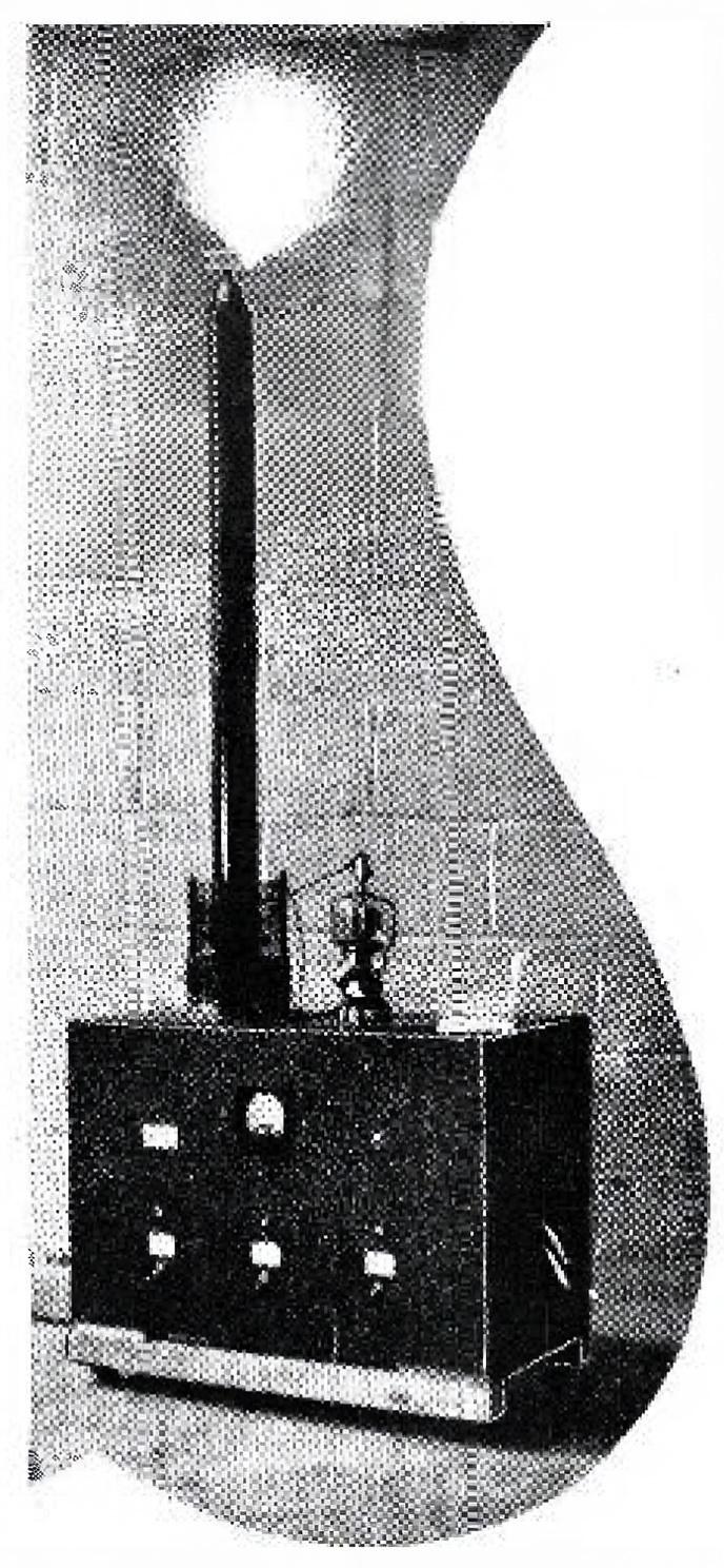
Experimentation with the coil will reveal the many fascinating demonstrations which can be performed, such as the lighting of fluorescent and neon tubes without wires; in fact the energy of the discharge sufficient to ignite candles and paper, or to drive a pinwheel balanced on the discharge point. Even the smallest coil never fails to astound and interest onlookers with such feats as these.
Science teachers, Scoutmasters, Den Mothers, and amateur magicians, will all find a Tesla coil unit an interesting project to build and use.