
Plans
Simplified Tesla Coil
Gives 200,000-volt Current for Many Dazzling Experiments
By Kenneth M. Swezey
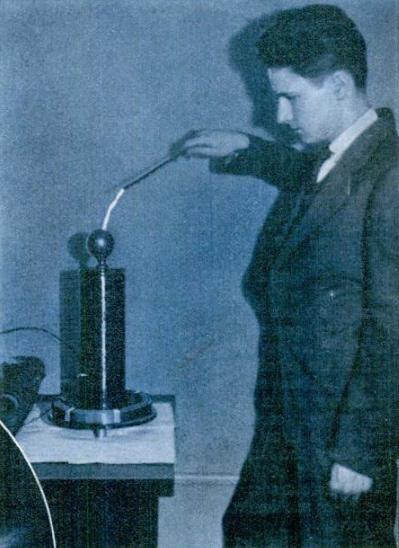
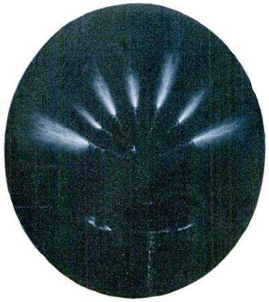
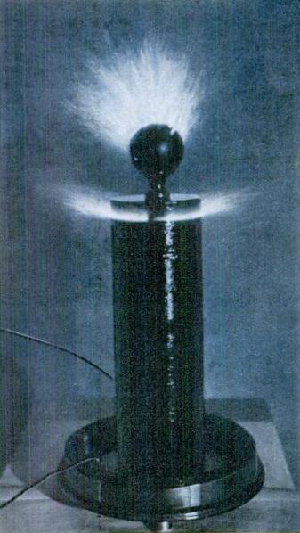
Purple streamers of sparks from eight to ten inches long, potentials of several hundred thousand volts, beautiful fountains of brush discharge, wireless lights, high-frequency currents that may be taken into the human body without harm and used to perform dozens of amazing experiments — all these are at the instant command of the home experimenter who builds a simple resonance transformer or what is usually called a Tesla coil.
Of all the shapes and sizes a Tesla coil may take, the present coil has been chosen as particularly inexpensive, easy to construct, and yet large enough to perform most of the more spectacular experiments. If the prospective builder happens to be a radio amateur of the old "spark" days and still has the remains of his transmitting apparatus, the whole outfit may be assembled for less than $1.50. If he must buy or build a high-voltage transformer, condenser, spark gap, and tuning inductance, the cost may climb from $10 upward, depending upon the type of equipment desired.
The first essential is a high-voltage transformer capable of stepping up the 110-volt A.C. house current to from 10,000 to 15,000 volts. An old 1/4- or 1/2-kw. amateur transmitting transformer is ideal, or a transformer of the kind used for lighting neon signs may be used. Used or rebuilt transformers of the latter type may be bought quite cheaply from any neon sign repair company. For home workers who wish to build their own, an article on the construction of step-up transformers will appear in a later issue.
A flat tuning coil, consisting of a spiral of about twenty turns of copper or brass ribbon, 1/2 in. wide and spaced about 1/4 in. apart, with a sliding contact, is perhaps the most compact and easily adjusted. Such coils, as parts of discarded amateur or Navy transmitters, may often be picked up in second-hand electrical shops for less than a dollar. A coil simpler to build may be made by winding a helix of twenty turns of No. 6 bare copper wire on a cylindrical form of notched wooden strips, 8 in. in diameter, with the turns spaced about 3/8 in. The lower end of the coil should be connected to a binding post. The other connection may be made by means of a spring clip, which may be snapped on the heavy wire at any position required.
Any type of spark gap familiar to the old radio amateur may be used. A quenched gap is preferable where silence and utmost efficiency are desired. A rotary gap is almost as effective. An ordinary straight gap, however, with a small electric fan blowing across the electrodes, will serve satisfactorily.
Upon the condenser depends a great deal of the final effectiveness of the entire outfit. For compactness combined with minimum loss, the high voltage mica condenser stands in a class by itself. If the experimenter can obtain a mica condenser with a working voltage exceeding that of his transformer secondary, and a capacity between .002 and .004 microfarads, his
condenser problem will be solved.
His next best bet is to make a condenser with metal foil and glass plates. Select fourteen 8 by 10 in. photographic plates that are free from large air bubbles and scrape off the emulsion after wetting the plates with warm water. Next, cut twenty-eight pieces of thin copper foil or heavy tinfoil as shown.
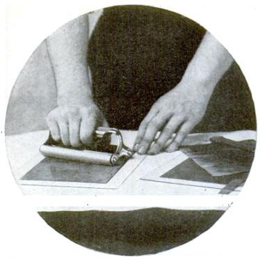
Some builders apply the metal-foil coatings to the plates with shellac, but the writer has had better results with beeswax. Heat the plates gently in an oven or at a distance above an electric grill or gas flame, and rub a piece of beeswax over one side of one of the plates until a thin coating has been distributed over the entire surface. Before it cools, quickly center one of the pieces of foil on the wax coating and press it into firm contact by means of a photographic roller. The lug should extend 1 1/4 in. above the top of the plate. While the plate is still warm, turn it over and apply the wax and foil to the other side, this time attaching the foil so that the lug comes up at the opposite side.
When seven plates have been completed, bind them tightly together with insulating tape. As a further precaution against brush discharges around the edges, this unit may be boiled for a few minutes in a mixture of one part beeswax to one part rosin, or in one of the compounds made by insulating supply houses especially for the purpose. If properly assembled, seven lugs should be grouped at each side. A hole should be punched near the ends of the lugs, and each group clamped tightly together with a brass bolt and nuts.
The second unit of seven plates should be treated similarly. A wooden spacer, 5/8 in. thick and the size of the plates, should be placed between them, and the two units connected as shown in series- parallel. If desired, the whole condenser may be put into a wooden box (built preferably without nails or screws), which has been thoroughly impregnated with hot wax or insulating varnish, and the terminals led to binding posts on the top.
The materials required for the Tesla coil itself include a cardboard tube, 4 in. in diameter and 13 in. long; 1/2 lb. of No. 28 double cotton-covered wire; about 10 1/2 ft. of copper or brass ribbon, 1 in. wide; three ordinary small spools; two binding posts; corrugated cardboard; 1/2 pt. insulating varnish; a brass bed ball; a wooden disk for the base, 10 in. in diameter; wooden disks for the top and bottom of coil; dowels, glue, and tape.
Because of the tremendous voltages produced, great attention must be paid to insulation. All the wooden parts and the cardboard tube should be thoroughly dry and treated with several coats of air-drying insulating varnish, which may be obtained wherever electric motor and transformer repair work is done. Dowels should be used instead of nails or screws for holding the parts together.
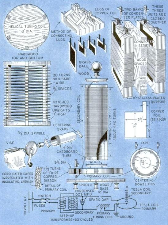
For the base, the writer used a circular bread board. Its legs are three spools, held by glue and dowels. A wooden disk, about 1/2 in. thick and large enough to fit snugly within the cardboard tube, is doweled to the center of the upper surface of the base.
The primary coil may next be constructed. Cut enough strips of corrugated cardboard about 3/4 in. wide to make a length totaling about 9 ft. Soak these thoroughly in the varnish. Bend a neat loop in one end of the copper strip, large enough to pass the bolt that will hold one of the binding posts. Then, using a round can or box 7 1/2 in. in diameter as a form, start winding the primary. Wind just 4 2/3 turns, with the varnished corrugated board as a separator. At the outer end of the strip, bend another loop for the bolt of a second binding post. After sliding the coil from the form, the turns may be bound tightly together by six bands of adhesive tape. Half a dozen 3/16-in. dowels, set into the base in a circle of 7 1/2 in. outer diameter, will hold the primary.
The secondary may be wound either by hand, on a lathe, or with a simple winding rig. The latter may be constructed in a few moments with the aid of a small vise, hand drill, curtain rod, four brads, and two pieces of wood, arranged as shown. The brads are spaced far enough apart to fit the inside of the tube snugly. If the holes in the middle of the end pieces fit the rod tightly enough, the tube will be held securely by friction. The end of the rod may be supported in any convenient way to steady it, if necessary.
Before winding, give the tube another coat of varnish, and begin when this is still tacky. Puncture a small hole 1/2 in. from the left end of the tube, and pass about 6 in. of the No. 28 wire through it. Then wind a single layer of wire from that point to a point 1/2 in. from the other end, bringing the final end of the wire out through a tiny hole as at the beginning. It is best to apply a coat of varnish to the tube immediately ahead of each 2 or 3 in. of winding, so that the underside will be permeated. When completed, the outside should be given two coats.
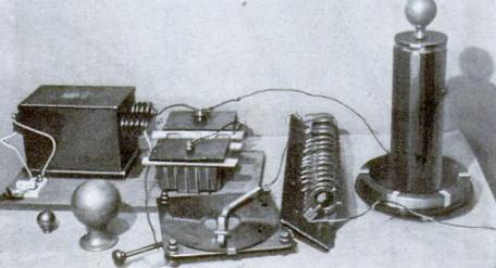
The assembly is clearly shown in the drawings and photographs. The lower end of the secondary winding should be connected under the head of the bolt that secures the binding post on the inner turn of the primary. The upper end should be secured to the bolt on which the bed ball is screwed. Make these leads as short as possible.
With coil and exciting apparatus completed, you need merely connect them up and adjust them. Few precautions are necessary, except that one should keep from touching any part of the exciting circuit while the coil is in operation. Always open the switch before making adjustments of the spark gap, condenser, or tuning coil. Although the current from the secondary of the Tesla coil is absolutely harmless and almost without sensation, the current from the exciting circuit may give one an unpleasant jolt.
To get the longest and heaviest spark from a Tesla coil, it must be tuned and otherwise adjusted as carefully as a radio transmitter. The finer the apparatus used, the more precisely it must be adjusted, so experiment patiently to find the most effective adjustments of the spark gap and tuning coil. With one adjustment of the clip of the tuning coil, you may get no spark at all; by moving the clip merely half a turn, a 4-in. streamer may dart from the ball of the Tesla coil, and another quarter turn may double this.
