Plans
Electronic Flame
Is this a new discovery? Or is it an effect that goes back to Tesla's days?
By THOMAS E. FAIRBAIRN
While a friend and I were talking over ham station W8SYK to another ham in Australia, a large flame started shooting off the capacitor stator of the antenna-coupling tank. At the same time we lost our contact and shut down the transmitter as quickly as possible to prevent breakdown. I remarked to my friend that this was such a different flame that I wanted to see it again — would he please turn the transmitter back on?
Upon a closer look I noticed that even though the flame was burning vigorously, the transmitter remained properly tuned and suffered no damage.
The sight of metal burning like a stick of wood was very curious. If one metal burned so might others, if they were placed at the point on the transmitter where the flame was first noticed. I took a 6-inch piece of No. 14 copper wire and put it on this point on the capacitor stator. With a slight retuning of the final amplifier and antenna coupling tank, the end of the copper wire burst into a long, bright green flame about six inches high and very hot. The wire melted and burned down very slowly. About this time an r.f. arc jumped across the plates of the variable antenna output capacitor and shorted out the high-voltage power-supply transformer. Our experiment was over, and my friend would not renew it.
Nearly two years later I acquired this transmitter, to conduct experiments to see if the flame would reappear and at the same time try to find out what it was.
I knew that if I was to prevent the transformer or something else from burning out, the unit used must be so changed as to prevent arc-overs and overloads. The antenna output and
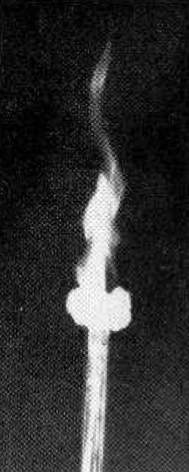
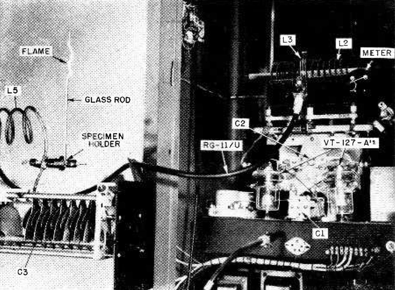
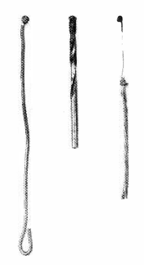
coupling circuits were redesigned as pictured in the photo opposite. Note also the schematic diagram of this output circuit in Fig. 1. The main change in this transmitter was increasing the spacing between the antenna output tuning capacitor plates from one-quarter inch to one inch. The antenna was completely removed to give the highest Q in the output tank. A specimen holder was also put at a convenient high-voltage, high-impedance point on the antenna output tank coil, so metal and glass rods to be burned could be held firmly and changed easily.
A new phenomenon?
What is this electronic flame? It does not appear to be an electric or r.f. arc, but looks more like a flame of a torch or burner. Only a conductor of electricity such as zinc, steel, tungsten, or leaded glass, will burst into flame. Such nonconductors as wood or paper will burn only when placed in the electronic flame. To find out what the electronic flame is, many experiments were conducted.
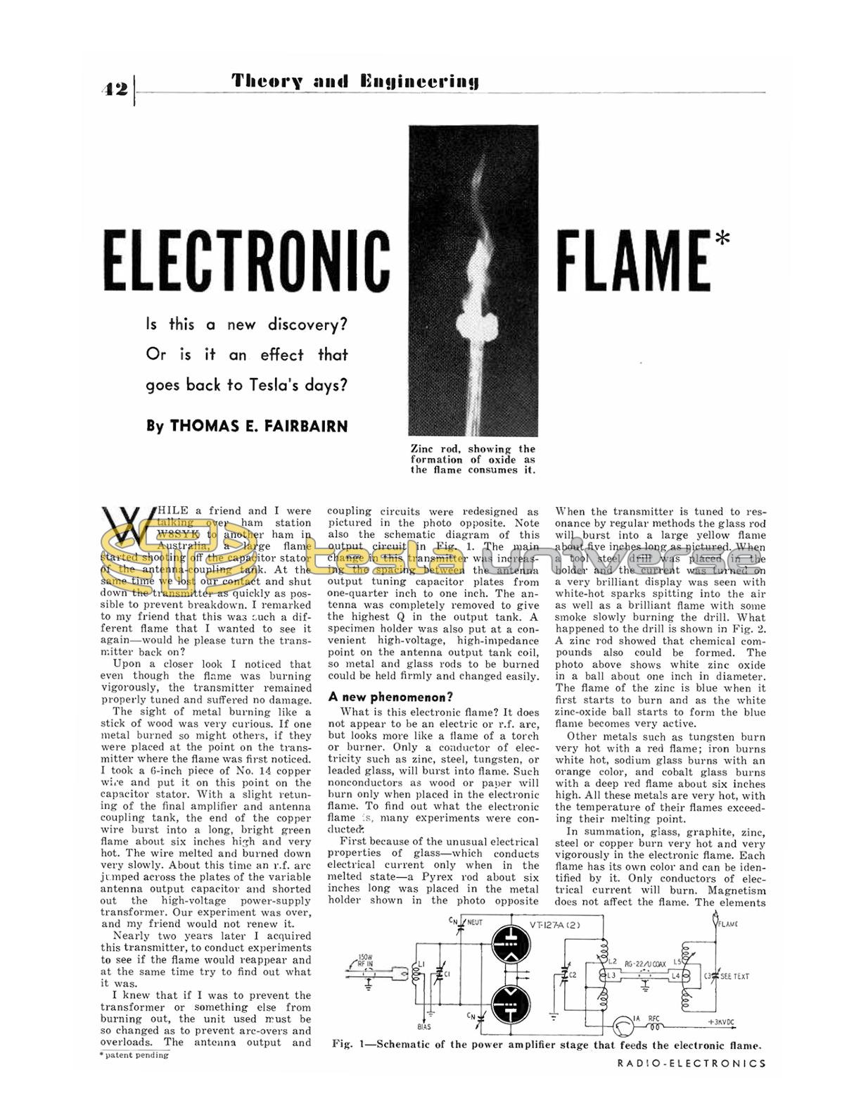
First because of the unusual electrical properties of glass — which conducts electrical current only when in the melted state — a Pyrex rod about six inches long was placed in the metal holder shown in the photo opposite.
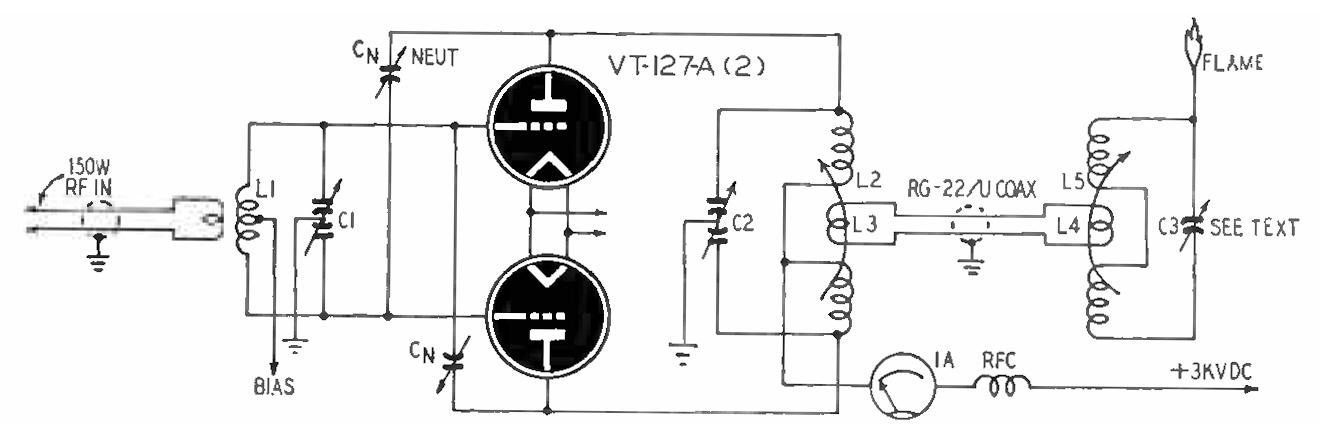
When the transmitter is tuned to resonance by regular methods the glass rod will burst into a large yellow flame about five inches long as pictured. When a tool steel drill was placed in the holder and the current was turned on a very brilliant display was seen with white-hot sparks spitting into the air as well as a brilliant flame with some smoke slowly burning the drill. What happened to the drill is shown in Fig. 2. A zinc rod showed that chemical compounds also could be formed. The photo above shows white zinc oxide in a ball about one inch in diameter. The flame of the zinc is blue when it first starts to burn and as the white zinc-oxide ball starts to form the blue flame becomes very active.
Other metals such as tungsten burn very hot with a red flame; iron burns white hot, sodium glass burns with an orange color, and cobalt glass burns with a deep red flame about six inches high. All these metals are very hot, with the temperature of their flames exceeding their melting point.
In summation, glass, graphite, zinc, steel or copper burn very hot and very vigorously in the electronic flame. Each flame has its own color and can be identified by it. Only conductors of electrical current will burn. Magnetism does not affect the flame. The elements that are burned reduce very slowly to ash, compounds, and melted material. The flame needs little or no oxygen (but might need a supporting gas about it). Compounds can be formed which are nonconductors of current. When the plate current is turned off the flame goes out but comes on again when the current is turned on. The electronic flame looks and acts like any other fire.
No complete transmitter schematic is given, for the results can be duplicated by any 1,000-watt, high-Q short-wave transmitter, with a high-voltage output tuning capacitor a necessity. The master oscillator is a crystal-controlled 6AC7 oscillating at about 7 megacycles. It drives a 6Y6 doubler-amplifier. The 5U4 supplies B plus for these two tubes. A 6L6 doubler drives the 813 buffer amplifier at 14 mc. It supplies the final amplifier tubes, a pair of VT-127-A's, with 150 watts of grid drive. The buffer amplifier is supplied 400 volts d.c. by a pair of 816's, and the final amplifier gets 3,000 volts d.c. from a pair of 866's. A 5U4-G also furnishes grid bias for the class C final amplifier. The VT-127-A's are surplus radar tubes similar to the Eimac 100T's and 304T's. They can stand very high plate currents. This is why we can allow the electronic flame to burn in excess of 1½ ampere plate current without damage to the tubes.
The output frequency of the unit is located in the 14-megacycle amateur band. The station was operated by Wardel Mitchel, W8SYK, during experiments. (Don't forget FCC regulations with respect to unmodulated carriers. Editor) The output of the final amplifier is coupled to the output circuit by a coaxial cable RG-11/U. This coupling circuit is so designed as to prevent the 3,000-volt d.c. to the final amplifier tuning tank from getting into the flame output circuit. Refer again to Fig. 1. It is important to maintain a very high Q in the output circuit where the rod to be burned is placed.
To find the right place to put the rod to be burned on the output tank I suggest that a large highly insulated screwdriver be touched to the high-voltage point to find the place where the largest arc is drawn off. Be very careful, as an r.f. burn is bad and will jump as far as an inch to one's hand. Keep your hand back on the handle!
Tuning is the same as that of any transmitter except I recommend that the final amplifier and output tuning tanks be tuned with the final amplifier plate current off. It is well known that the final amplifier plate current can be tuned by watching the very small dip in the final plate current meter even though near zero. The output tank can be tuned the same way after the rod to be burned is properly placed except we tune the output tank for the least amount of movement of the plate current meter when it is dipped by the final plate tank capacitor. After the current is turned on, touch up the final and output tanks by regular methods for the best resonance.
When resonance is reached, the end point of the metal or glass rod will burst into fire. The coupling from the final amplifier tank to the output tank can also be tuned for more or less coupling. The greatest coupling does not always make the biggest flame. About one half coupling is recommended for maximum Q.
Why does the glass or metal rod act as it does? When a parallel-resonant circuit is tuned to resonance it has a very high impedance and consequently a high voltage across it. If the Q of our circuit is high then there will be a very high voltage at a very low current. across the output tank at resonance.
This voltage is in the millions. Oscillating at 14 megacycles, there is no way to radiate this high power. A small six-inch rod when placed at this point offers very little impedance to the resonant tank; therefore the Q of the circuit is not affected and the high voltage will be at the end point of the rod. This high-potential energy has no place to go other than out the end point of the rod into the air. As this energy is rushing out the small end point of the rod the rod is bound to get hot. It appears that it is not the current that is making the rod hot enough to burn, but the high voltage constantly pounding away at 14,000,000 times per second. Almost anything would get hot if you pounded it at that pressure and frequency!
The temperature of the flame depends on the type of metal burning. Metals with a higher melting point will take a fraction of a second longer to reach that melting point. As long as a metal has not reached its melting point its end point remains small, giving the energy leaving it a small path out, but when its melting point is reached, the end is much larger and offers less resistance to the outgoing energy and the temperature will stay at the vapor and melting point of the metal used.
The only factor that would seem to limit the temperatures that may be attained would be the amount of energy used and the pressure behind it. In this experiment 1,000 watts appear to be sufficient to burn almost any metal.
Upon closer examination of the contents of the flame it was found to contain vapor of the element that was emitting the flame as well as a mixture of the oxide of that element. The light that comes from the flame is that which is given off from any metal when it burns, plus some ionization of the vapor by the r.f. in the tank circuit.
END
* patent pending
Editor note: See the follow-up article in Radio Electronics of February, 1953.