TCBA Volume 16 - Issue 1
Page 13 of 18
Classical Two-Coil System
Bert Hickman
2523 Stonewall Ave., Woodridge, IL 60517
[email protected]
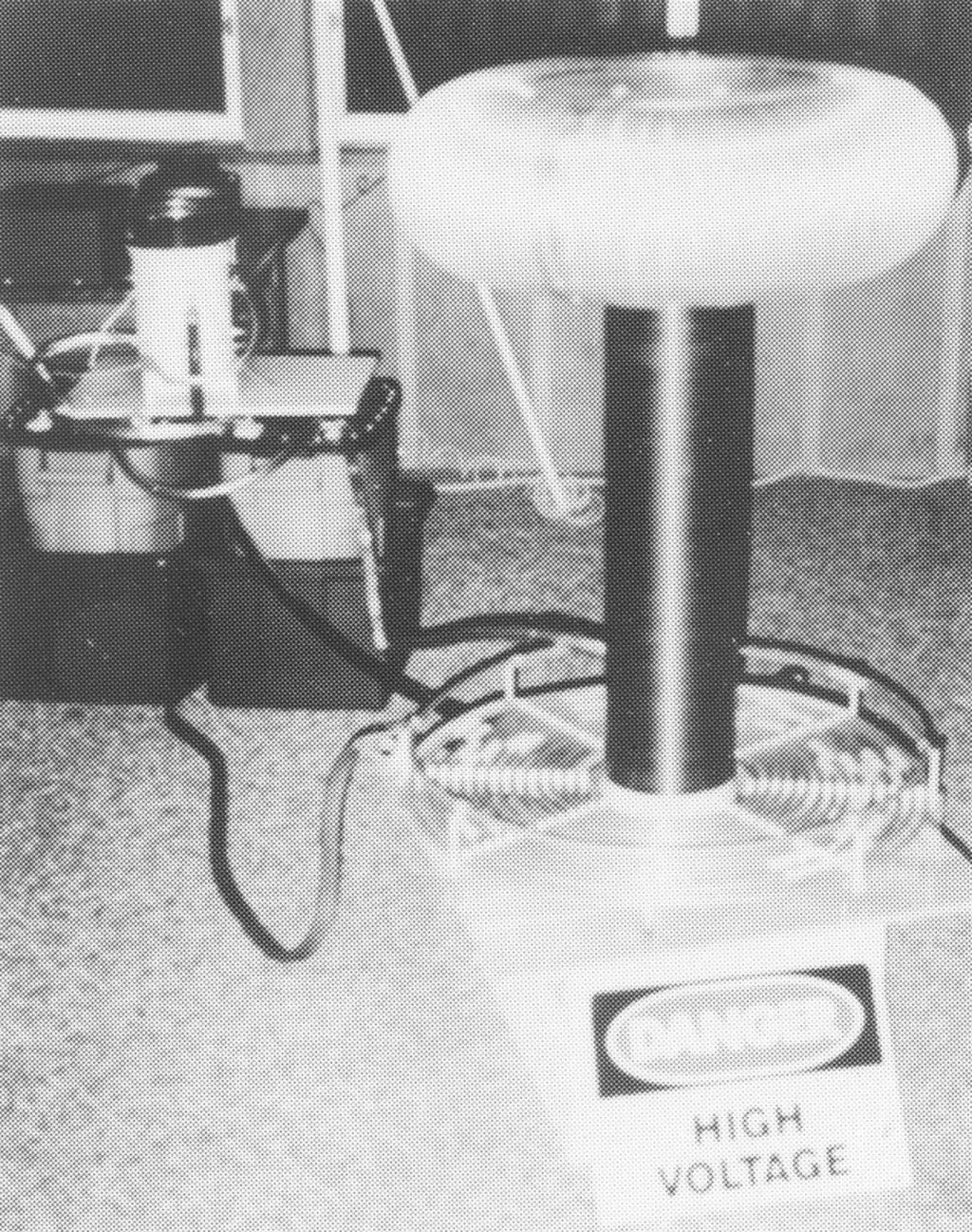
I've just completed a classical two-coil system powered by three 15 kv, 30 ma neon sign transformers through a 140 volt Variac. The 6" diameter secondary has a 24" winding of #22 AWG double Formvar coated with six layers of polyurethane. A 26" diameter toroid is mounted on top consisting of two cake pans and an 8' length of 8" diameter flexible aluminum ducting. The loaded resonant frequency of the coil is about 180 kHz. The secondary base is grounded to a dedicated RF ground consisting of two eight-foot ground rods connected via #4 AWG wire. The ground measures 15.5 ohms with respect to AC/water-pipe ground, and I am considering adding one or more ground rods to reduce this even further.
The primary consists of a planar spiral of 3/8" copper tubing, supported by 9" long 1/2" x 2" Lexan bars, each drilled to hold 1/4" Delrin rods which separate and hold the primary turns. The 14-turn primary coil is on 5/8" turn spacing, and has a 25" outer diameter. Short pieces of 3/8" ID HDPE tubing are slipped over adjacent turns when using an alligator clip tap to prevent shorting to adjacent turns. The measured coupling coefficient is about 0.15.
I also designed and built two home-made 0.011 uF stacked-plate pulse capacitors. These use 4-mill LDPE film (3' X 50' rolls) as the dielectric, and 12" wide heavy-duty aluminum foil for plates. Internally, each capacitor is constructed from 4 identical low-inductance stacked-plate modules. The LPDE material comes folded on itself four times in a roll that is approximately 9.25" wide by 50' long. This material is cut into 14" lengths and visually inspected for defects. One capacitor takes about 7 rolls (at about $3.50/roll). The aluminum foil is cut into 12" x 12" pieces, the overlapping area being 7.5" x 12", leaving a 1" margin along three edges.
Two layers (i.e., 8 four-mil thicknesses of LDPE) are used between alternate foil layers, and 37 of these foil-dielectric-foil sandwiches are stacked on top of each other per module. Sheet PVC and nylon spacers are used to secure the stack together, and 1/8" aluminum angle iron, bus bars, and sheet metal screws are used to terminate the foil along the long edges (12" length). Four modules are then mounted together and connected in series via heavy tinned copper braid and sheet metal screws between the aluminum bus bars. The whole assembly (now about 7" x 11" x 15") is placed inside an 8" x 12" x 18" high LDPE Rubbermaid Roughneck container with a matching lid. The LDPE is oriented with long-axis vertical to permit expulsion of entrapped air without requiring pumpdown.
High current terminations (3/8" threaded brass rod) are brought through the lid via nylon mounting plates, the unit is filled with about 4.5 gallons of Shell Diala-X transformer oil, and the lid secured with a buna-N gasket and sheet metal screws. Each assembled capacitor weighs about 40 pounds and clocks in at about 0.011 uF with each designed to withstand over 20 kvAC input with no problem. After a 3-week break-in period at gradually increasing run times and input voltage, I am now running these in parallel at up to 17.5 kv RMS (140 volt input to the neons), with the total gap set at 400 to 550 mils, thus far, they have taken all my “pounding” with no sign of abnormal behavior.

