
TCBA Volume 16 - Issue 1
Page 7 of 18
A Three-Phase Tesla Coil
V. Miljevic
The Institute of Nuclear Sciences “Vinca”, Atomic Physics
Laboratory, P.O. Box 522, 11001 Belgrade, Yugoslavia
Nikola Tesla's autobiography MY INVENTIONS states that he began his work on high frequency machines in 1889. His high frequency machine known today as a Tesla coil is still a remarkable generator of high voltages. As the instant of time when the rotary spark gap shortens the primary is a random event, with respect to the charging voltage of its capacitor, a Tesla coil functions unevenly. Nikola Tesla increased the number of rotating spark gaps in his coils in order to remove this deficiency as well as for other reasons. It is not known to this author whether or not Tesla ever used polyphase currents to power his transformers. A preliminary study of applying three phase to power a Tesla coil is reported in this present work.
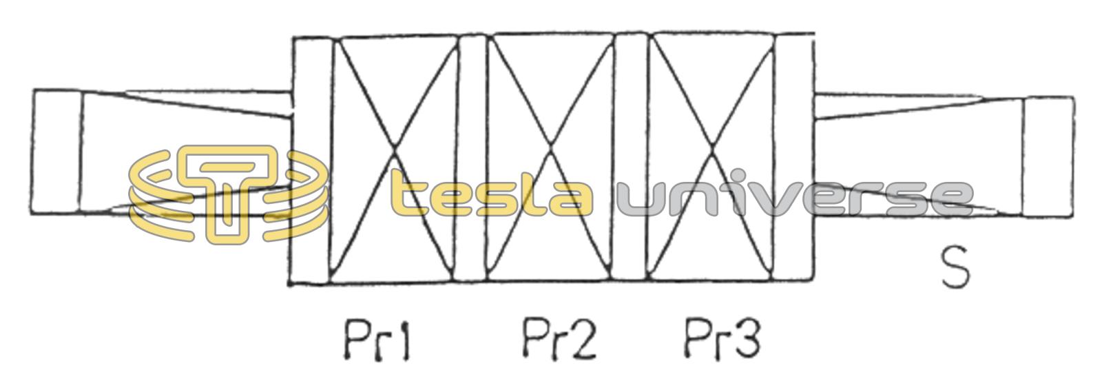
The three-phase Tesla coil (3PTC) has three identical primary cylindrical coils and a single secondary cylindrical coil, all placed coaxially as shown in Figure 1. Additional data for coils in our 3PTC are given in Table 1. The primary coils are wound on a tube made with insulating properties providing a very high voltage breakdown. And distances between adjacent primary coils and between the primary and secondary coils ensures that no voltage breakdown occurs between them. In addition, the geometry of the primary and secondary coils was chosen in order to provide maximum coupling.
Table 1. Data for coils in our three-phase Tesla coil (3PTC).
| Quantity | Primary x 3 | Secondary |
|---|---|---|
| Diameter [cm] | 24.7 | 11.05 |
| Length [cm] | 11.4 | 90.2 |
| Number of turns | 20 | 1605 |
| Diameter of wire [mm] | 2.5 | 0.5 |
| Resistance [Ω] (measured) | 0.106 | 48.5 |
| Inductance [mH] (measured at 1 kHz) | 0.108 | 32.75 |
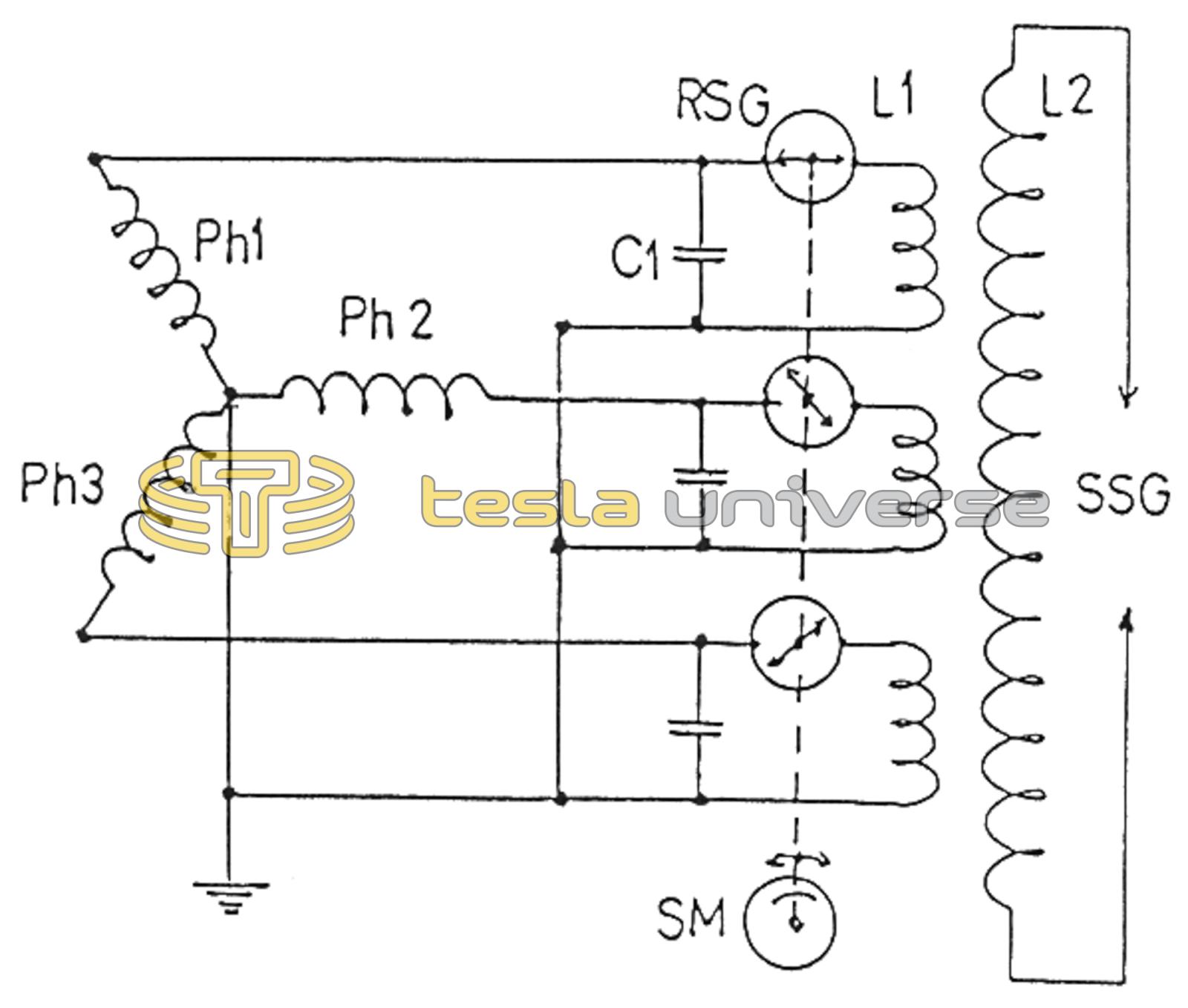
The electric schematic of 3PTC is shown in Fig. 2. Each primary has its own capacitor of 5000 pF/12 kV and a two-electrode rotating spark gap. All three spark gaps are placed on the same shaft of a synchronous motor at relative angles of 120 degrees. The motor rotates at 3000 rpm synchronously with the AC power supply. The spark gaps can be adjusted angularly with respect to the shaft during its rotation. This ensures a discharge at each of the three capacitors at the instant of its maximum charge voltage. The phase shifts in operation of spark gaps ensures that an active primary of the 3PTC does not influence the other two. This was proven by experiment. Thus, when one primary is active the other two primary circuits are open as their spark gaps are inactive. The Tesla coil was loaded at the secondary with a spark distance of 15 cm.
Similar results are obtained when one primary coil is used instead of three coils and three rotating spark gaps are replaced by one with three two-electrode gaps. The electric schematic is shown in Figure 3. If the flanges of the primary and secondary coils are aligned, then such a configuration of coils is similar to the conventional Tesla coils as seen in Fig. 4, but with three-phase power supply as in the previous case.