
TCBA Volume 4 - Issue 1
Page 16 of 18
Distributed Capacity and Its Effect
By Samuel Cohen
Distributed capacity may be defined as the capacity existing between turns of a helical coif. It may also exist in straight conductors where the electrostatic capacity is between the conductor and the earth, or between two adjacent conductors.
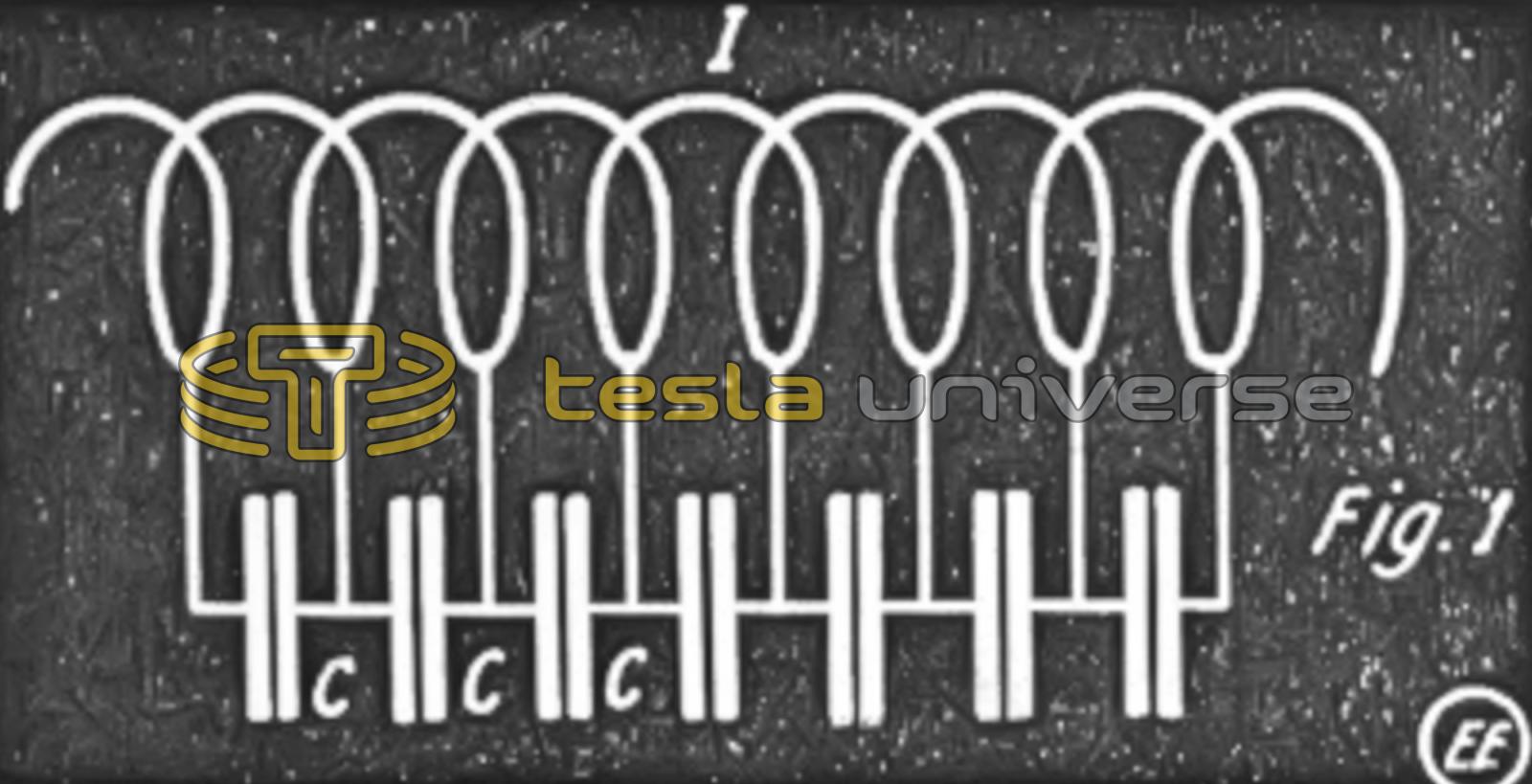
It can be shown by actual experiment that a difference of potential exists between adjacent turns. This potential difference creates an electrostatic field and energy is stored between the conductors.
A condenser is a device which stores electrostatic capacity. It is evident therefore that a condenser is formed, the plates of which are the adjacent conductor turns. The capacity is stored in the space between each turn of the coil and over all of the turns, therefore the capacity is distributed over the entire conductor.
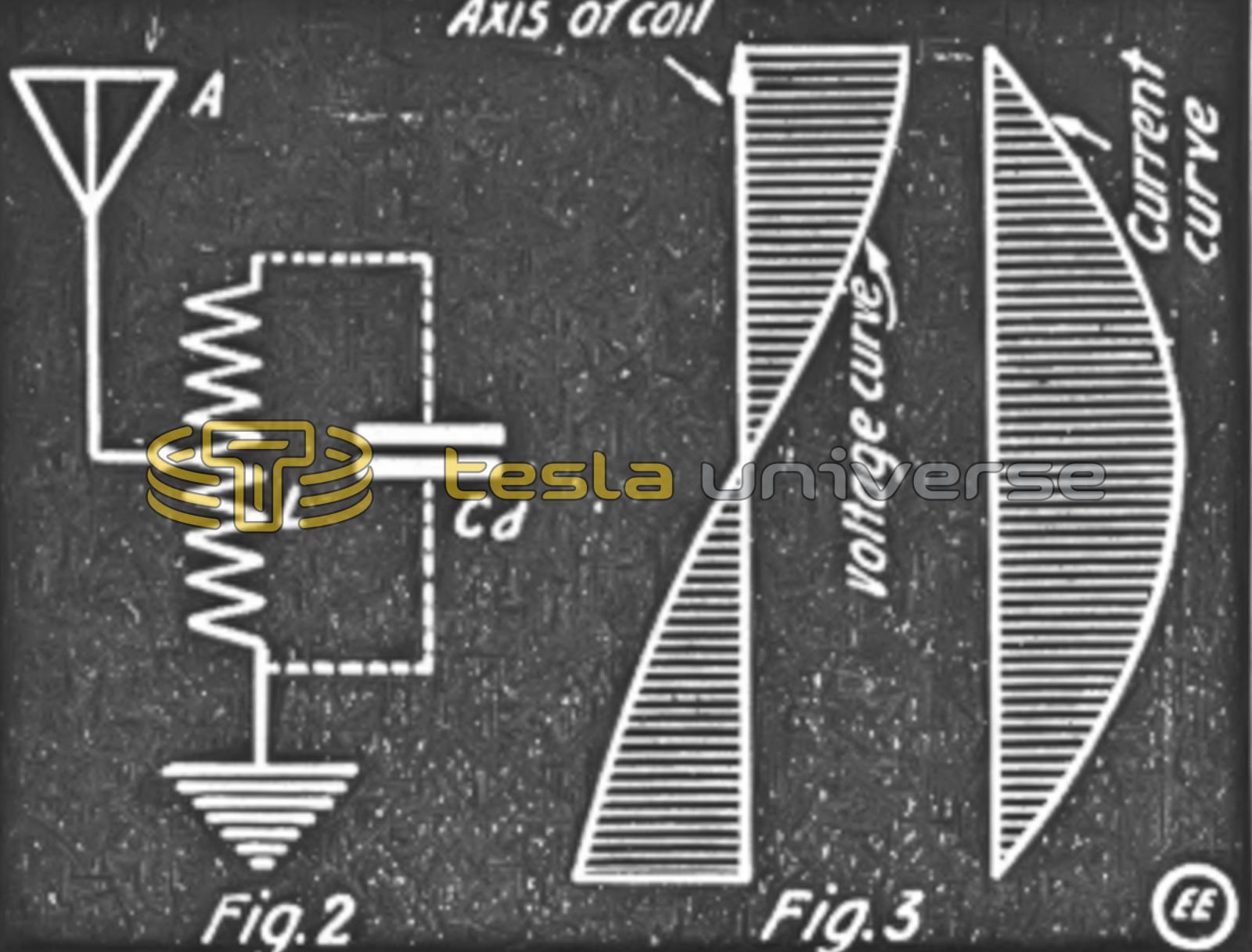
Referring to Fig. 1, it will be seen how distributed capacity is related to coils. Increasing the length of the coil, increases the distributed capacity as it is seen that the number of condensers are increased. Since increasing the number of condensers in parallel increased the capacity, therefore we may consider all the parallel condensers as one large capacity shunted across the inductance, as indicated in Fig. 2.
When capacity and inductance are linked in a circuit we have an oscillatory circuit, and the period of vibration of such a system is directly proportional to the square root of the product of the inductance and capacity multiplied by a constant. Expressing the above in an algebraic form we have:

Here n = period of vibration of the system. The wave length of the above current is,
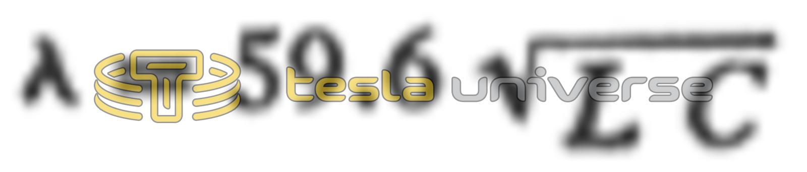
where L and C are the inductance and capacity.
It is evident therefore that since the coil has distributed capacity that the coil is an oscillatory circuit in itself, and it was found by actual experiment that when properly excited by a high frequency current, it will oscillate, the period of which depends upon the magnitude of the units of inductance and capacity.
The true wave length of a circuit containing a large inductance and shunted with a capacity is not the same when calculated with formula (2) but the exact wave lengths will be as exprest in the following relation:
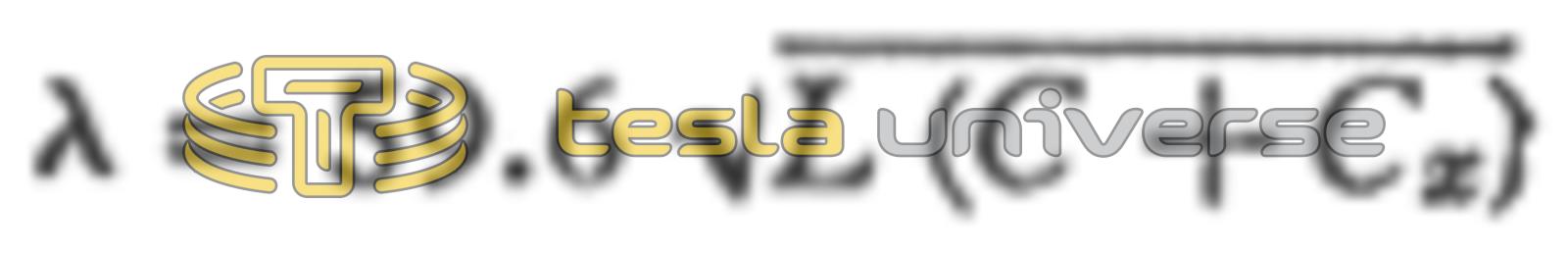
Where C is the capacity of the shunted condenser and to it we add the distributed capacity of the coil Cx. Solving for Cx we have:

Calling the total capacity Ct equation (4) becomes:

It has also been found by actual experiment that whenever a large coil was excited by radio frequency current it will oscillate in its own period just the same as a coil shunted with a condenser and excited. The current and voltage relation of this coil is exactly the same as for a Hertz oscillator, where the current value is a maximum at its center and minimum at the ends, while the voltage is maximum at the ends and minimum at the center. Fig. 3 shows graphically this relation of the coil.
The best means for determining the distributed capacity is by actual measurement. The essential instruments necessary for this kind of work are calibrated inductance and capacity which may be obtained from a wave meter, a high frequency buzzer and an additional condenser. The instruments are connected as indicated in Fig. 4. The coil, whose distributed capacity is to be determined, is placed in a single loop of wire L, Fig. 4, which is excited by the buzzer, Placing the wave meter inductance L2 near the excited circuit the condenser C2 is turned for indicating resonance. When the point of resonance is obtained the period of vibration of both circuits are the same T = T. Substituting the observed values in the equation,

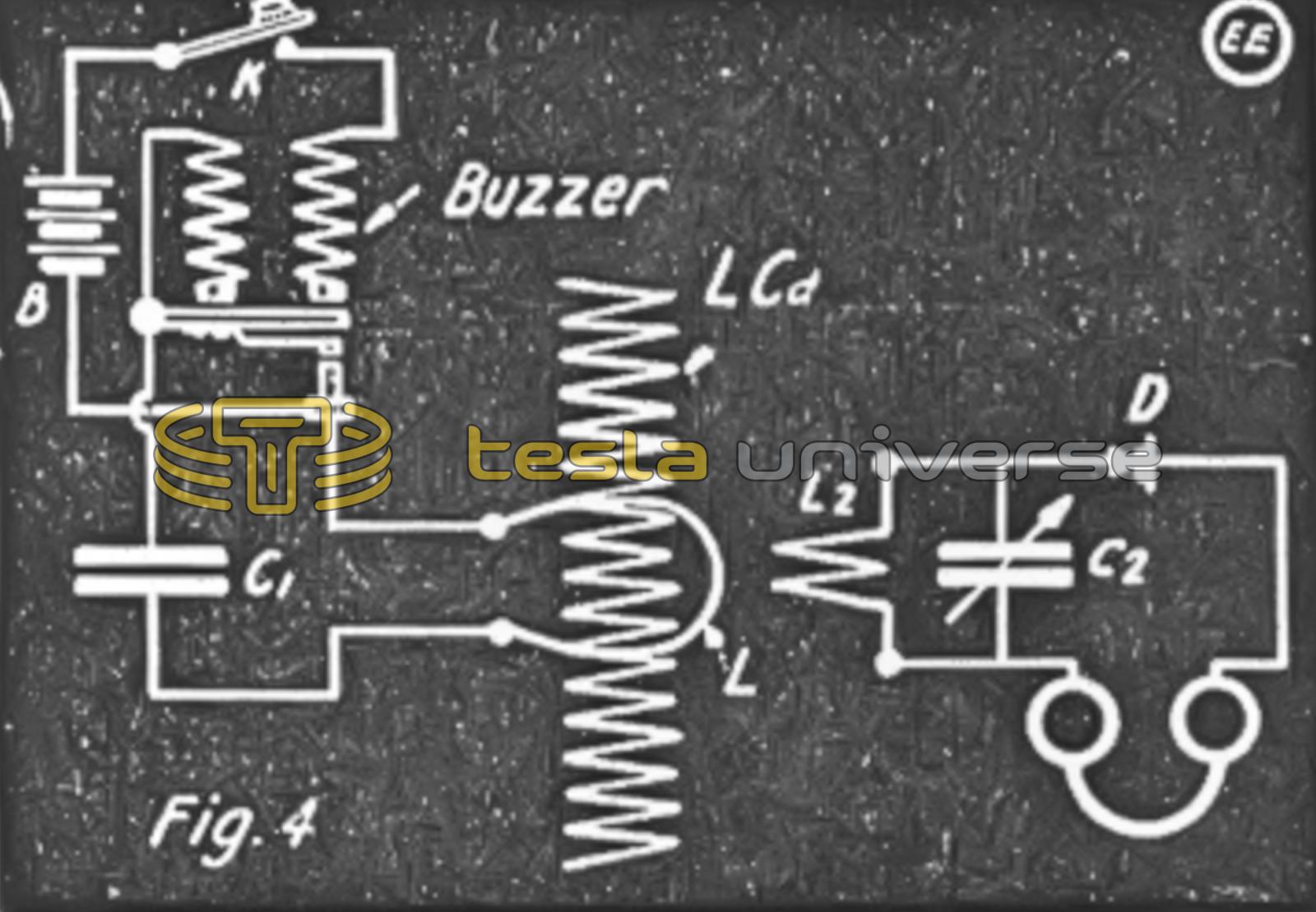
Where
- L2= the inductance of wave meter coil in centimeters.
- C2 = capacity of condenser at point of resonance in m.f.
- L1 = inductance of coil, the distributed capacity of which is class to be found.
It is advisable before starting to measure the distributed capacity of a coil, to determine before-hand the magnitude of the figures so as to enable us to procure approximately the proper inductances and capacity in the wave meter circuit. It can either be found by judging it from experience or else by actually calculating its value. An approximate formula has been derived by Drude for the calculation of the distributed capacity as follows:
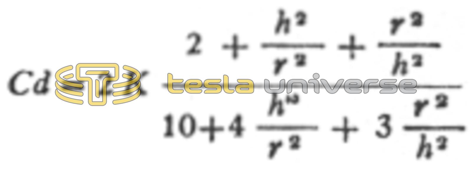
Where “h” and “r” are the length and radius of the coil respectively. The constant K is obtained from the following table, which is for air core coils.
| h/2r | K |
|---|---|
| 6 | 1.81 |
| 5 | 1.64 |
| 4 | 1.74 |
| 3 | 1.37 |
| 2 | 1.26 |
| 1 | 1.12 |
| 0.8 | 1.10 |
| 0.6 | 1.07 |
| 0.4 | .94 |
| 0.2 | .69 |
| 0.1 | .49 |
| 0.05 | .28 |
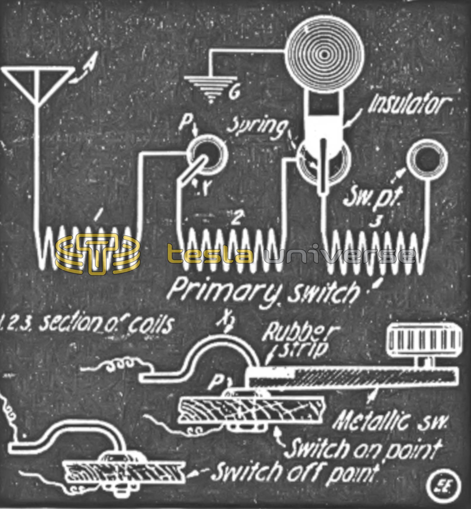
Having determined the distributed capacity of a coil, what are we going to do with this? The only thing that we are trying to do with it is to decrease its value in the coil as much as possible. There are several methods of decreasing the so-called dead-end effects in radio coils. The best and most practical way is to disconnect the portion of the winding which is not in use and this is what, may be accomplished by employing a special switch arrangement on the coil. A highly ingenious switch which serves the purpose very nicely was described in the “Question Box” of the June 1916 issue of this journal. For those who have not seen this copy, the accompanying reproduction is made, Fig. 5. The construction is very simple and the drawing is self-explanatory.
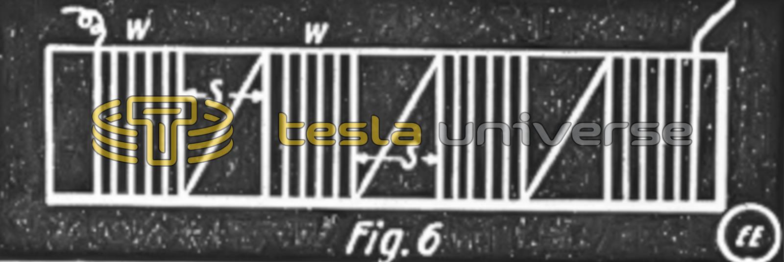
The effect of distributed capacity and dead-end effect is more pronounced in long coils and it is advisable to wind such coils in sections as shown in Fig. 6. It has been found that a considerable amount of distributed capacity is eliminated by such a method of winding and it should be done in every case where it is possible, especially on secondaries of loose couplers. The reason for reducing the distributed capacity is self-apparent, as the capacity varies inversely as the thickness of the dielectric between the conducting mediums. Thus the capacity is reduced by increasing the distance between sections. It will be an ideal inductance if each turn of the coil is separated from its neighboring turn, say, one-thirty-second of an inch each. The distributed capacity of such a coil would be very small as compared to a coil with the wires close together.