Nikola Tesla Articles
Building the Worlds Largest Tesla Coil History and Theory
Electrical and Computer Engineering Departtnent Durland Hall Kansas State University Manhattan, Kansas 66506
Abstract
A faculty advisor and a group of eight engineering honors students have embarked on a plan to design, build, and test the world's largest Tesla coil. Analysis will be performed using the program TCTUTOR by James Corum, with modifications. Power MOSFETs will be used to excite the coil. Hall effect sensors will be used to monitor voltage waveforms. Optical fibers will be used to transmit control signals and measured quantities to and from the Tesla coil. In addition to the educational benefits of the project, it is hoped that the coil will be able to generate ball lightning.
Introduction
Nikola Tesla (1856-1943) was one of the most important inventors in human history, with over 700 patents. He invented the induction motor and our present system of three-phase power in 1888 [1]. He invented the Tesla coil, a resonant air-core transformer, in 1891. Then in 1893, he invented a system of wireless transmission of intelligence. Although Marconi is commonly credited with the invention of radio, the U.S. Supreme Court decided in 1943 that the Tesla Oscillator patented in 1900 had priority over Marconi's patent which had been issued in 1904 [2]. Therefore Tesla did the fundamental work in both power and communications, the major areas of electrical engineering. These inventions have truly changed the course of human history.
After Tesla had invented three-phase power systems and wireless radio, he turned his attention to further development of the Tesla coil. He built a large laboratory in Colorado Springs in 1899 for this purpose. The Tesla secondary was about 51 feet in diameter. It was in a wooden building in which no ferrous metals were used in construction [2]. There was a massive 80-foot wooden tower, topped by a 200-foot mast on which perched a large copper ball which he used as a transmitting antenna. The coil worked well, producing bolts of artificial lightning over a hundred feet long. Tesla then abandoned the Colorado Springs Laboratory early in 1900, having learned what he needed from that facility, and also having become somewhat unpopular as a result of frequently knocking the local sub-station off line.
Since that time, it appears that no one has built a Tesla coil of both the size and performance of the Colorado Springs coil. Apparently the only coil of that size was built by Robert Golka at Wendover Air Force Base in Utah [3] and later moved to facility near Leadville, Colorado [4,5]. The original purpose of this coil was to produce artificial lightning for testing the effects of lightning striking aircraft in flight. Golka determined that the average voltage produced in Utah was about 10 million volts, with the highest voltage observed being 25 million volts. Operation was spectacular, even if not quite at the level of the Colorado Springs coil.
When Golka's coil was moved to Leadville, however, it performed very poorly. Golka was basically unable to properly tune the coil. There has been considerable speculation over the reasons for the difference in performance, but one problem seems to be that we still do not have adequate theoretical models for the design and operation of Tesla coils. What appeared to be minor differences in location and construction caused a major decrease in performance. The number of variables was simply too large to allow for a purely experimental optimization of performance before the coil was dismantled and moved early in 1990.
Some work on theoretical models has been performed by high energy physicists r6,7,8,9 and 10]. They are interested in high voltage capacitor discharges for research in plasma physics and in the production of pulsed particle or radiation beams. ·The most common way of producing such high voltage discharges is the Marx circuit, in which capacitors are charged in parallel to a lower voltage and then discharge in series through a number of air gaps. The Marx circuit requires the capacitor bank to be divided into sub-banks well-insulated from each other and from ground. A Tesla coil offers an alternative method of charging the high voltage capacitors. Discharges are reported in the range of 100,000 amps at l million volts, with one report of 2,500,000 [7]. These models are all lumped parameter models.
The brothers James and Kenneth Corum have made considerable advances in the full understanding of Tesla coils in the past few years [11, 12]. They have pointed out that lumped parameter models are not adequate for all situations. Sometimes a distributed circuit analysis must be made. In this case, the Tesla coil secondary and another component called the extra coil are considered as sections of transmission lines. This explains some of the effects in an elegant manner. They have written a sophisticated computer program, TCTUTOR, to analyze Tesla coils. They have also performed considerable historical research into Tesla's notes made on his facility in Colorado Springs [13].
There still remains a need for better instrumentation to measure the voltage and current waveforms at various points in the circuit, so that the theories can be validated. The logical technology for this high field environment is fiber optics, where small sensors can be mounted at appropriate places on the coil, and the information transmitted over optical fibers to the measurement equipment. Preliminary tests indicate that voltages can be readily measured by an electric field sensor [14]. It should be possible to measure current with a Hall effect sensor and a similar fiber optic system.
There is also a need for a better system to supply power to the Tesla coil, instead of the spark gap used for the last century. A system is needed to switch hundreds of amperes at thousands of volts in one microsecond or less. Spark gaps can basically handle any voltage and current, but the switching times tend to be slow. Power MOSFETs have adequate switching times, but the voltage and current ratings are lower than desired. It may be that adequate ratings can be obtained by parallel and series combinations of power MOSFETs. If not, then at least power MOSFETs can be used to drive the Tesla coil during tuning adjustments, using spark gaps for full power operation [15].
Tesla Coil Theory
The references contained detailed analyses of Tesla coils, especially the lumped circuit model, so only a summary will be presented here.
A classical Tesla coil contains two stages of voltage increase. The first is a conventional iron core transformer with high per unit impedance that steps up the available line voltage to a voltage in the range of 12 to 50 kV, 60 Hz. The second is a resonant air core transformer (the Tesla coil itself) which steps up the voltage to the range of 200 kV to 1 MV. The output is at a frequency much higher than 60 Hz, perhaps 500 kHz for the small units an 80 kHz for the large units. The very large Tesla coils, such as the Colorado Springs coil and Golka's coil, have a third stage of voltage increase, called the extra coil. This steps the voltage up to the range of 10 to 25 MV.
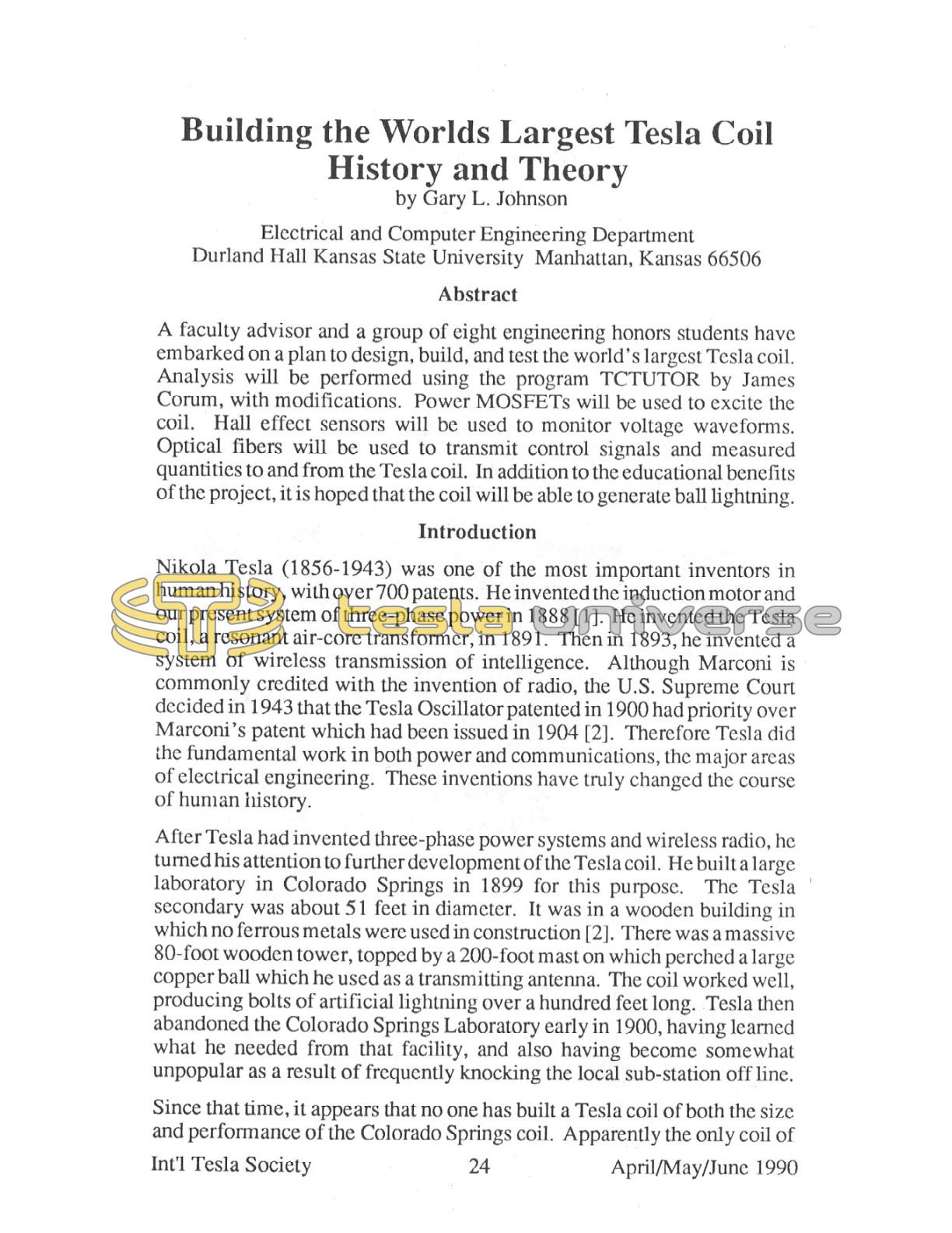
The circuit for the classical Tesla coil is shown in Fig. 1. The spark gap G is fixed in the small coils and rotary in the large coils. The primary capacitor Cl is a low loss capacitor, rated at perhaps 20kV, and usually made from mica. The primary coil L1 is usually made of 2 to 5 turns for the small coils an 1 or 2 turns for the large coils. The secondary coil L2 consists of perhaps 25 turns for the large coils and as many as 400 turns for the small coils. The secondary capacitance C2 is not a discrete commercial capacitor but rather is the distributed capacitance between the windings of L2 and the voltage grading structure at the top of the coil (a toroid or sphere) and ground. This capacitance changes with the volume charge density around the secondary, increasing somewhat when the sparks start. It also changes with the surroundings of the coil, increasing as the coil is moved closer to a metal wall. This may have been one of the reasons that Golka's coil worked better in Utah than in Colorado, because the metal walls were closer to the coil in Colorado.
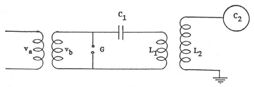
When the gap is not conducting, the capacitor C1 is being charged in the circuit shown in Fig.2, where just the central part of Fig.1 is shown. The inductive reactance is much smaller than the capacitive reactance at 60 Hz, so L1 appears as a short at 60 Hz and the capacitor is being charged by the iron core transformer secondary.
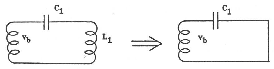
When the voltage across the capacitor and gap reaches a given value, the gap arcs over, resulting in the circuit in Fig.3 The shorted gap splits the circuit into two halves, with the iron core transformer operating at 60 Hz and the circuit to the right of the gap operating at a frequency (or frequencies) determined by Cl, L 1, L2, and C2. It should be noted that the output voltage of the iron core transformer drops to zero while the input voltage remains the same, as long as the arc exists. The current through the transformer is limited by the equivalent series impedance shown as Rs+ jXs in Fig.3 The neon sign transformers typical] y used for small Tesla coils use conventional transformers with per unit impedances in the range of 0.05 to 0.1. A transformer with a per unit impedance ofO. I will experience a current of ten times rated while the output is shorted. Most transformers do not survive very long under such conditions. Golka was not alone in burning out some of his transformers. The solution is to include additional reactance in the input circuit.
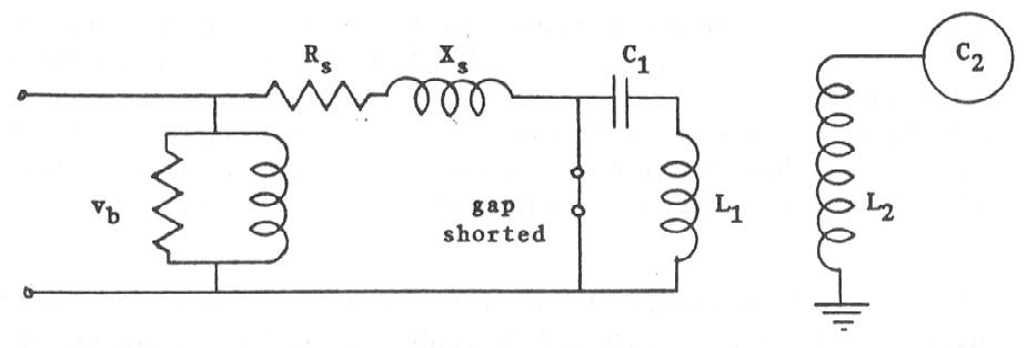
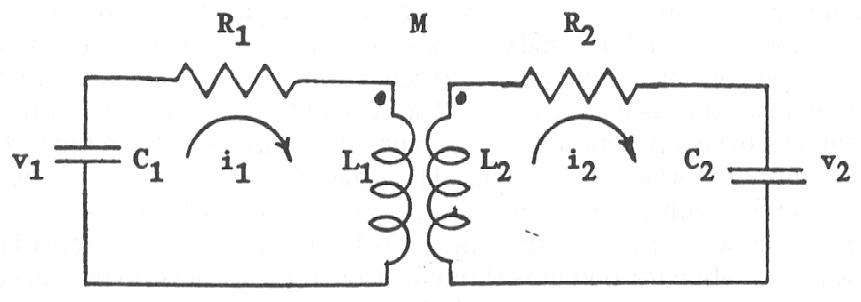
The equivalent circuit of the Tesla coil while the gap is shorted is shown in Fig.4. R 1 and R2 are the effective resistances of the air cored transformer primary and secondary, respectively. The mutual inductance between the primary and secondary is shown by the symbol M. The coefficient of coupling is well under unity for an air cored transformer, so the ideal transformer model used for an iron cord transformer in the first course on energy conversion does not apply here.
At the time the gap arcs over, all the energy is stored in C1. As time increases, energy is shared among C1, L1, C2, L2, and M. The total energy in the circuit decreases with time because of losses in the resistances R1 and R2. With proper design (proper values of C1, L1, C2, L2, and M) it is possible to have all the energy in C1 transferred to the secondary at some time t1. That is, at tl there is no voltage across C1 and no current through L1. If the gap opens at tl, then there is no way for energy to get back into the primary. No current can flow, so no energy can be stored in L1, and without current the capacitor cannot be charged. The secondary then becomes a separate RCL circuit with nonzero initial conditions for both C2 and L2. This circuit will then oscillate or 'ring' at a resonant frequency determined by C2 and L2. With the gap open, the Tesla coil secondary is simply. an RCL circuit, described in any text on circuit theory. The output voltage is a damped sinusoid.
If the gap is set to arc over at a voltage near the peak of the 60 Hz waveform, then there will be only one pulse per half cycle, or 120 pulses per second of energy being supplied to the air cored transformer, If the secondary is designed for a resonant frequency of 240 kHz, for example, then each pulse has to supply adequate energy to maintain oscillation in the secondary for 2,000 cycles. The duration of the arc is typically on the order of 10 micro seconds, or for 2 or 3 cycles of the output waveform. This means that the peak power flow during the arc may be a thousand times the average power flow when the gap is not conducting. This poses some problems regarding the size and strength of circuit components. This illustrates one of the basic problems with a spark gap. Even when the gap arcs several times in a cycle of the 60 Hz input, there are still relatively long periods when the secondary is 'coasting'.
This raises the question as to why we do not supply energy every cycle rather than some small fraction of the time. This would have several advantages:
- Peak power flow would be nearly equal to the average power flow.
- Peak input current would be much smaller.
- Output voltage would be more nearly sinusoidal.
- Harmonic content and electromagnetic interference would be reduced. It appears that this can be done with power MOSFETs, at least up to moderate voltage and current levels.
The analysis of the lumped parameter circuit is straightforward, if a bit tedious. However, at least the secondary is bettered modeled as a distributed parameter circuit. It basically appears to be a quarter wave transmission line terminated by a capacitor C2. An open-circuited quarter wave section has a voltage maximum and a current minimum at the open circuit, and a current maximum and a voltage minimum at the input. The voltage increase from the input to the open circuited output is basically equal to the standing wave ratio. The output voltage cannot exceed the input voltage times the turns ratio for the 1 um pcd circuit model, but no such limit exists for the distributed model.
Questions
All of this discussion raises a number of questions which can only be answered by careful measurements on several Tesla coils, ranging in size from perhaps 0.3 m diameter by 1 m tall to one similar in size to the Colorado Springs coil. Among the questions are the following:
How good is the quarter wave transmission line model for the Tesla coil secondary? Does the input impedance vary with frequency as would be expected for a transmission line? What is ·a good way to experimentally determine the input impedance? Where do the most dielectric losses occur, in the conductor insulation, the wood frame, or the earth itself? Does the computer code developed by the Corums describe the circuit adequately? Can Power MOSFETs be used in place of the spark gap? Other questions are certain to be raised as we get further into the project.
Status
As of May, 1990, the project team has acquired:
- A secluded 25 acre site for testing coils.
- 23 cable TV poles, about 20 feet long.
- About 10,000 feet of bare 6 gauge copper wire.
- A large double wall copper screen room, to protect the oscilloscope and other instrumentation.
- A secondary of 174 turns of insulated 8 gauge copper wire, 0.3 m diameter by 1 m high.
- A four turn primary of 0.5 inch copper tubing.
- Two top loading toroids
- Various fiber optic, power MOSFET, and power op-amp circuits. Testing of the 1 m coil will start in the fall semester, 1990, as well as the design for the next coil, which will probably be about 6 m diameter by 4 m high. These dimensions should make it the largest Tesla coil in existence. Once we are confident that theory and experiment agree for this size of coil, plans will be started for a still larger coil, one at least slightly larger than the Colorado Springs coil.
Acknowledgements
The eight students involved in this project are Jon Anderson, John Doughty, Glen Handke, Daniel Jensen, John Mosimann, Troy Ramser, Ross Stites, and Ted Wald.
References
1. Terbo, William H., 'Opening Address', Proceedings of the Tesla Centennial Symposium. Colorado Springs, Colorado, August 9-12, 1984.
2. Jones, H.W., 'Project Insight - A Study of Tesla's Advanced Concepts', Proceedings of the Tesla Centennial Symposium, Colorado Springs, Colorado August 9-12, 1984
3. Golka, Robert K., 'Long Arc Simulated Lightning Attachment Testing Using a 150 kW Tesla Coil', IEEE International Symposium on Electromagnetic Compatibility, October 9-11, 1979, San Diego, CA, pp.150-155.
4. Grotz, Toby, 'Project Tesla - An Update', Tesla Coil Builders Association News, Volume 9, No.1, January, Febuary, March, 1990, pp.16-18.
5. Peterson, Gary L., 'Project Tesla Evaluated', The Journal of Power and Resonance, The International Tesla Society, Volume 6, No. I, Jan/Feb/March 1990, pp.25-34.
6. Finkelstein, David, Phillip Goldberg, and Joshua Shuchatowitz, 'High Voltage Impulse System', The Review of Scientific Instruments, Volume 37, Number 2, February 1966, pp.159-162.
7. Hoffmann, C.R.J ., 'A Tesla Transformer High-Voltage Generator', The Review of Scientific Instruments, Vol.46, No.I, January 1975, pp.1-4.
8. Boscolo, I.,G. Brautti, R. Coisson, M. Leo, and A. Luches, 'Tesla Transformer Accelerator for the Production of Intense Relativistic Electron Beams', The Review of Scientific Instruments, Vol.46, No. I 1, November 1975, pp.1535-1538.
9. Luches, A. and A. Perrone, 'Coupled Marx-Tesla Circuit for Production of Intense Relativistic Electron Beams', The Review of Scientific Instruments, Vol.49, No.12, December 1978, pp.1629-1630.
10. Matera, Manlio, Roberto Buffa, Giuliano Conforti, Lorenzo Fini, and Renzo Salimbeni, 'Resonant Transformer Command Charging System for High Repetition Rate Rare-Gas Halide Lasers', The Review of Scientific Instruments, Vol.54, No.6, June 1983, pp.716-718.
11. Corum, J.F. and K.L. Corum, 'A Technical Analysis of the Extra Coil as a Slow Wave Helical Resonator', Proceedings of the 1986 International Tesla Symposium, Colorado Springs, Colorado, July 1986, published by the International Tesla Society, pp.2-1 to 2-24.
12. Corum, James, F., Daniel J. Edwards, and Kenneth L. Corum, 'TCTUTOR - A Personal Computer Analysis of Spark Gap Tesla Coils', Published by Corum and Associates, Inc., 8551 State Route 534, Windsor, Ohio, 44099, 1988.
13. Tesla, Nikola, 'Colorado Springs Notes', A. Marincic, Editor, Nolit, Beograd, Yugoslavia, 1978, 478 pages.
14. Johnson, Gary L., 'A Fiber Optic System For Measuring High Voltages', Extraordinary Science, P.O. Box 5636, Security, Colorado, 80911, Vol.1, No.1, Jan/Feb/March 1989, pp.5-9. Also printed in Tesla 89 Vol.5, No.2, March/April/May/June 1989, pp.14-21.
15. Johnson, Gary L., 'Using Power MOSFETs to Drive Resonant Transformers', Tesla 88, International Tesla Society, Inc., 330-A West Uintah, Suite 215, Colorado Springs, CO 80905, Vol.4, No.6, November/December 1988, pp.7-13. -GJ