Nikola Tesla Articles
Tesla's Alternating Generators for High Frequency
It has now become a common practice to run arc lamps by alternating or pulsating, as distinguished from continuous, currents; but an objection which has been raised to such systems exists in the fact that the arcs emit a pronounced sound, varying with the rate of the alternations or pulsations of current, for which, up to the present, no effective remedy has been found. This noise is due to the rapidly alternating heating and cooling, and consequent expansion and contraction, of the gaseous matter forming the arc which corresponds with the periods or impulses of the current. Another disadvantageous feature is found in the difficulty of maintaining an alternating current arc in consequence of the periodical increase in resistance corresponding to the periodical working of the current. This feature entails a further disadvantage namely, that small arcs are impracticable.
Theoretical considerations have led Mr. Tesla to the belief that these disadvantageous features could be obviated by employing currents of a sufficiently high number of alternations and his anticipations have been confirmed in practice. These rapidly alternating currents render it possible to maintain small arcs which, besides, possess the advantages of silence and persistency. The latter quality is due to the necessarily rapid alternations, in consequence of which the arc has no time to cool, and is always maintained at a high temperature and low resistance.
At the outset of his experiments Mr. Tesla encountered great difficulties in the construction of these machines. A generator of this kind is described here, which, though constructed quite some time ago, is well worthy of a detailed description.
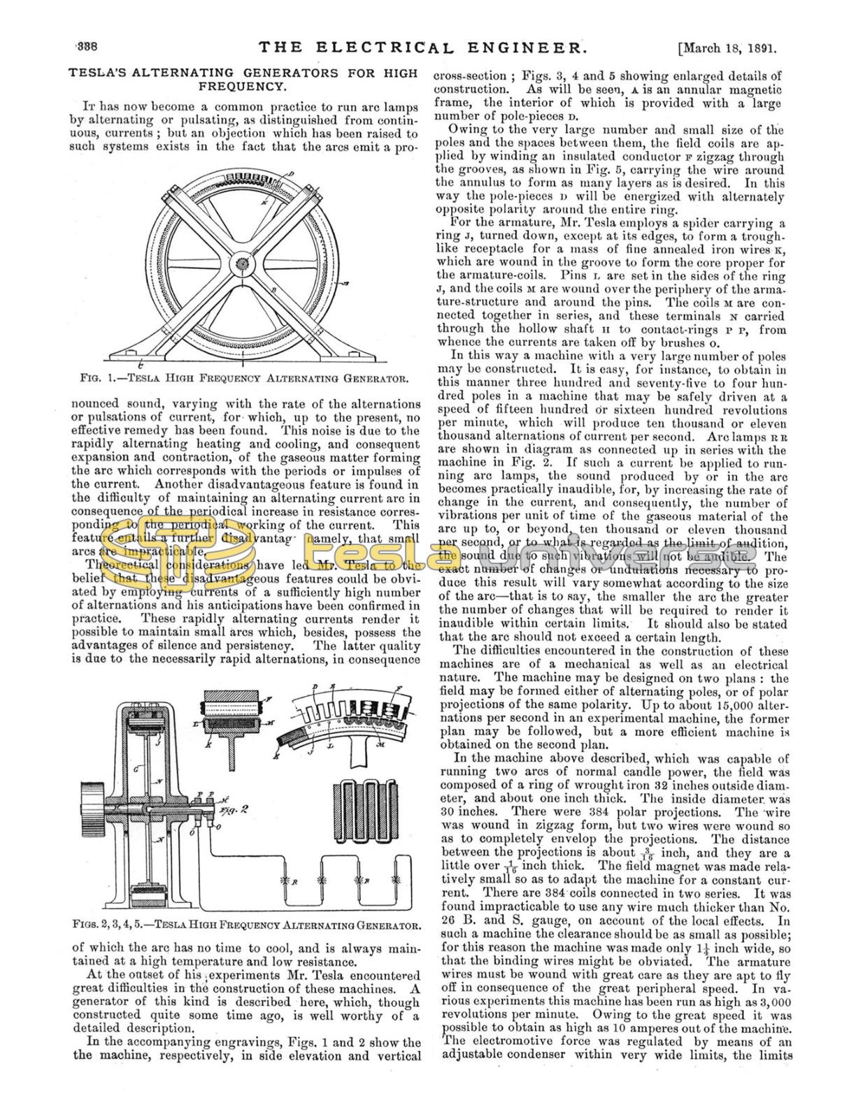
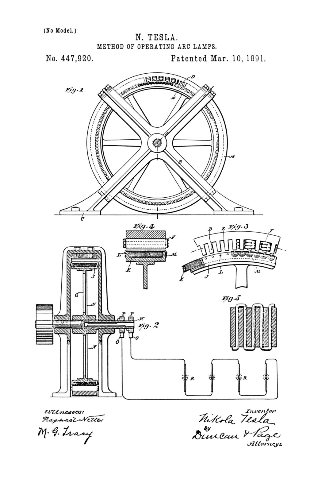
In the accompanying engravings, Figs. 1 and 2 show the machine, respectively, in side elevation and vertical cross-section; Figs. 3, 4 and 5 showing enlarged details of construction. As will be seen, A is an annular magnetic frame, the interior of which is provided with a large number of pole-pieces D.
Owing to the very large number and small size of the poles and the spaces between them, the field coils are applied by winding an insulated conductor F zigzag through the grooves, as shown in Fig. 5, carrying the wire around the annulus to form as many layers as is desired. In this way the pole-pieces D will be energized with alternately opposite polarity around the entire ring.
For the armature, Mr. Tesla employs a spider carrying a ring J, turned down, except at its edges, to form a troughlike receptacle for a mass of fine annealed iron wires K, which are wound in the groove to form the core proper for the armature-coils. Pins L are set in the sides of the ring J, and the coils M are wound over the periphery of the armature-structure and around the pins. The coils M are connected together in series, and these terminals N carried through the hollow shaft H to contact-rings P P, from whence the currents are taken off by brushes O.
In this way a machine with a very large number of poles may be constructed. It is easy, for instance, to obtain in this manner three hundred and seventy-five to four hundred poles in a machine that may be safely driven at a speed of fifteen hundred or sixteen hundred revolutions per minute, which will produce ten thousand or eleven thousand alternations of current per second. Arc lamps R R are shown in diagram as connected up in series with the machine in Fig. 2. If such a current be applied to running arc lamps, the sound produced by or in the arc becomes practically inaudible, for, by increasing the rate of change in the current, and consequently, the number of vibrations per unit of time of the gaseous material of the arc up to, or beyond, ten thousand or eleven thousand per second, or to what is regarded as the limit of audition, the sound due to such vibrations will not be audible. The exact number of changes or undulations necessary to produce this result will vary somewhat according to the size of the arc - that is to say, the smaller the arc the greater the number of changes that will be required to render it inaudible within certain limits. It should also be stated that the arc should not exceed a certain length.
The difficulties encountered in the construction of these machines are of a mechanical as well as an electrical nature. The machine may be designed on two plans: the field may be formed either of alternating poles, or of polar projections of the same polarity. Up to about 15,000 alternations per second in an experimental machine, the former plan may be followed, but a more efficient machine is obtained on the second plan.
In the machine above described, which was capable of running two arcs of normal candle power, the field was composed of a ring of wrought iron 32 inches outside diameter, and about one inch thick. The inside diameter was 30 inches. There were 384 polar projections. The wire was wound in zigzag form, but two wires were wound so as to completely envelop the projections. The distance between the projections is about 3/16 inch, and they are a little over 1/16 inch thick. The field magnet was made relatively small so as to adapt the machine for a constant current. There are 384 coils connected in two series. It was found impracticable to use any wire much thicker than No. 26 B. and S. gauge, on account of the local effects. In such a machine the clearance should be as small as possible; for this reason the machine was made only 1¼ inch wide, so that the binding wires might be obviated. The armature wires must be wound with great care as they are apt to fly off in consequence of the great peripheral speed. In various experiments this machine has been run as high as 3,000 revolutions per minute. Owing to the great speed it was possible to obtain as high as 10 amperes out of the machine. The electromotive force was regulated by means of an adjustable condenser within very wide limits, the limits being the greater, the greater the speed. This machine was frequently used to run Mr. Tesla's shop lights.
The machine above described was only one of many other types constructed. It serves well for an experimental machine, but if still higher alternations are required and higher efficiency is necessary, then a machine on a plan described in Figs. 6 to 9, is preferable. The principal advantage of this type of machine is that there is not much magnetic leakage, and that a field may be produced, varying greatly in intensity in places not much distant from each other.
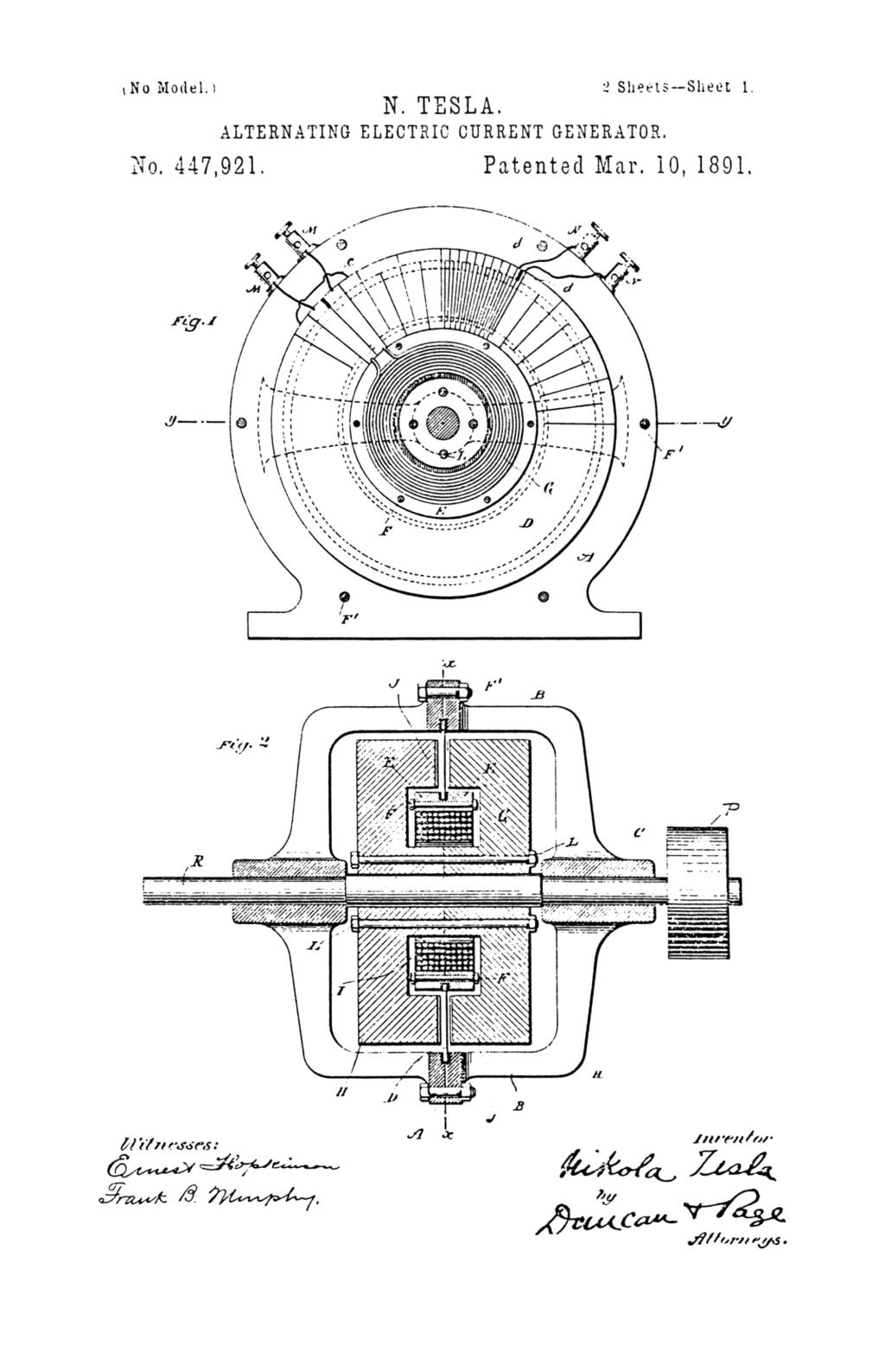
In these engravings, Figs. 6 and 7 illustrate a machine in which the armature conductor and field coils are stationary, while the field magnet core revolves. Fig. 8 shows a machine embodying the same plan of construction, but having a stationary field magnet and rotary armature.
The conductor in which the currents are induced may be arranged in various ways; but Mr. Tesla prefers the following method: He employs an annular plate of copper D, and by means of a saw cuts in it radial slots from one edge nearly through to the other, beginning alternately from opposite edges. In this way a continuous zigzag conductor is formed. When the polar projections are ⅛ inch wide, the width of the conductor should not, under any circumstances, be more than 1/32 inch wide; even then the eddy effect is considerable.
To the inner edge of this plate are secured two rings of non-magnetic metal E, which are insulated from the copper conductor, but held firmly thereto by means of the bolts F. Within the rings E is then placed an annular coil G, which is the energizing coil for the field magnet. The conductor D and the parts attached thereto are supported by means of the cylindrical shell or casting A A, the two parts of which are brought together and clamped to the outer edge of the conductor D.
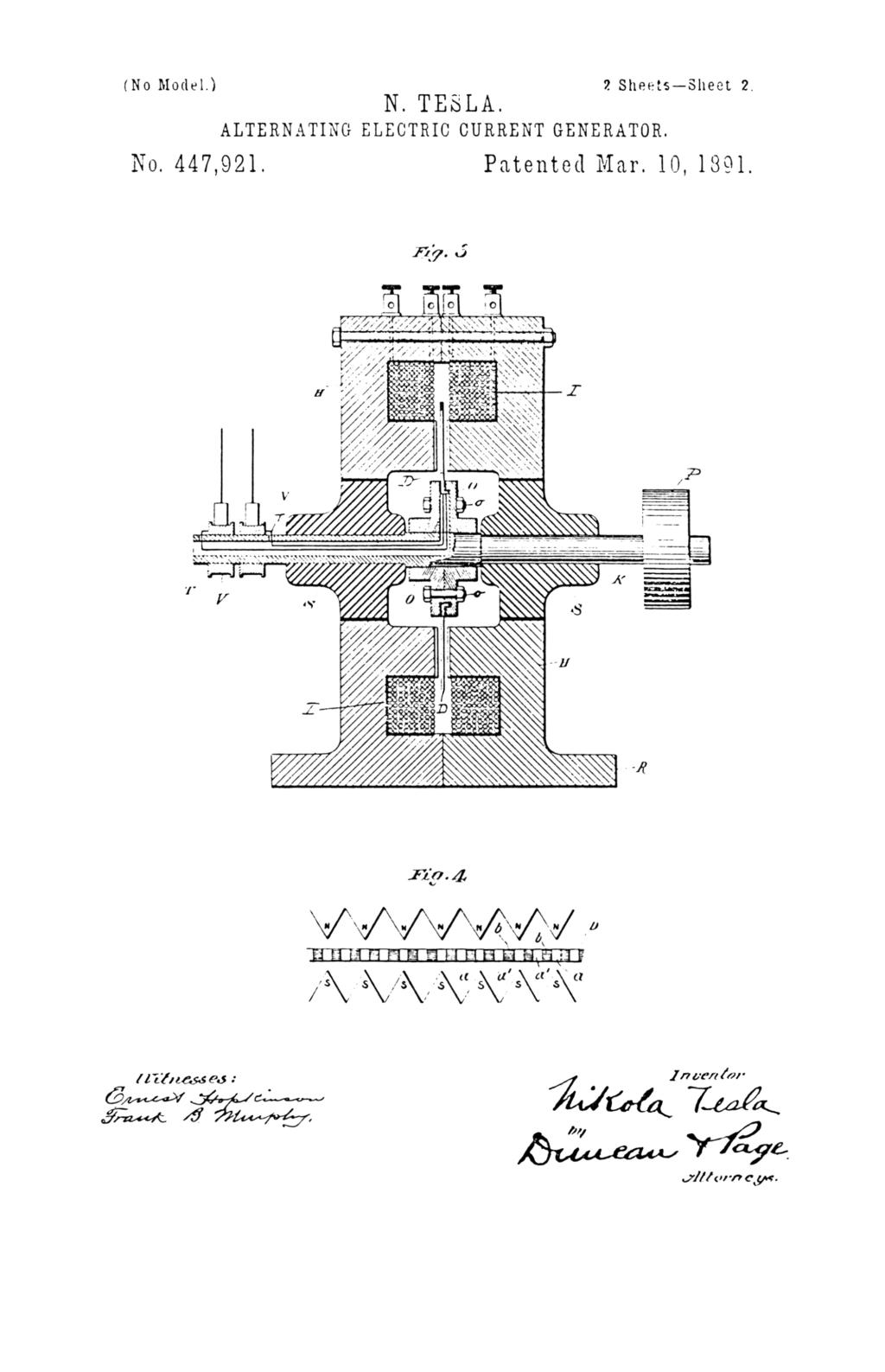
The core for the field magnet is built up of two circular parts H H, formed with annular grooves I, which, when the two parts are brought together, form a space for the reception of the energizing coil G. The hubs of the cores are trued off, so as to fit closely against one another, while the outer portions or flanges which form the polar faces J J, are reduced somewhat in thickness to make room for the conductor D, and are serrated on their faces. The number of serrations in the polar faces is arbitrary; but there must exist between them and the radial portions of the conductor D a certain relation, which will be understood by reference to Fig. 9, in which N N represent the projections or points on one face of the core of the field, and S S the points of the other face. The conductor D, is shown in this figure in section a a' designating the radial portions of the conductor, and b the insulating divisions between the same. The relative width of the parts a a' and the space between any two adjacent points N N or S S is such that when the radial portions a of the conductor are passing between the opposite points N S, where the field is strongest, the intermediate radial portions a' are passing through the widest spaces midway between such points and where the field is weakest. Since the core on one side is of opposite polarity to the part facing it, all the projections of one polar face will be of opposite polarity to those of the other face. Hence, although the space between any two adjacent points on the same face may be extremely small, there will be no leakage of the magnetic lines between any two points of the same name, but the lines of force will pass across from one set of points to the other. The construction followed obviates to a great degree the distortion of the magnetic lines by the action of the current in the conductor D, in which it will be observed the current is flowing at any given time from the centre toward the periphery in one set of radial parts a and in the opposite direction in the adjacent parts a'.
In order to connect the energizing coil G with a source of continuous current, Mr. Tesla utilizes two adjacent radial portions of the conductor D for connecting the terminals of the coil G with two binding posts M. For this purpose the plate D is cut entirely through, as shown, and the break thus made is bridged over by a short conductor C. The plate D is cut through to form two terminals d, which are connected to binding posts N. The core H H, when rotated by the driving pulley, generates in the conductors D an alternating current, which is taken off from the binding posts N.
When it is desired to rotate the conductor between the faces of a stationary field-magnet, the construction shown in Fig. 8 is adopted. The conductor D in this case is made in substantially the same manner as above described by slotting an annular conducting-plate. The field-magnet in this case consists of two annular parts H H, provided with annular grooves I for the reception of the coils. The flanges surrounding the annular groove are brought together, while the inner flanges are serrated, as in the previous case, and form the polar faces.
In a type of machine of this kind, constructed by Mr. Tesla, the field had 480 polar projections on each side, and from this machine it was possible to obtain 30,000 alternations per second. As the polar projections must necessarily be very narrow, very thin wires or sheets must be used to avoid the eddy current effects. Mr. Tesla has thus constructed machines with a stationary armature and rotating field, in which case also the field-coil was supported so that the revolving part consisted only of a wrought iron body devoid of any wire, and also machines with a rotating armature and stationary field. It is left to the judgment of the experimenter which plan is best to follow, each promising certain advantageous features. These machines may be constructed on the drum or disc plan, but the experience of Mr. Tesla shows that the latter plan is preferable.