Nikola Tesla Books
Observations of resonant rise on Westinghouse transformer.
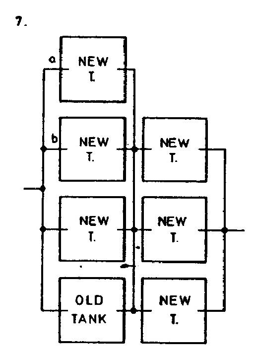
In order to observe the rise, the spark gap ordinarily used was made so large that the secondary discharge could not break through and the voltage on the primary, when throwing in the switch, was observed. Several values of primary capacity were experimented with. The diagram below indicates the position of the set of condensers on the right side looked at from the center of the building towards the entrance. On each side of the primary there were then 2 sets in series, the connections in one instance being indicated in diagram. In each old tank there were 16 jars, the capacity of each jar being 0.00334mfd. In each new tank there were 16 jars, capacity of each jar 10% more, being 0.00367 mfd. With tanks a and b off we have, calling C1 total capacity:
!$ {{1 \over C_{1}} = {2 \over {(0.00334 + 0.00367) 16}} + {2 \over {0.00367 \times 16 \times 3}}} !$
or
!$ {C_{1} = {0.00493 \over 0.144} = 0.03424} !$ mfd.
With this capacity on the secondary of the Westinghouse transformer the rise on the primary, as observed by Weston voltmeter, was from 102 to 122 volts. With tank b on each side added, the total capacity being C2, we have:
!$ {{1 \over C_{1}} = {2 \over {(0.00334 + 2 \times 000367)16}} + {2 \over {0.00367 \times 48}} = {1 \over 0.08544} + {1 \over 0.088}} !$
and from this C2 = 0.04336 mfd. In this case the rise was from 102 to 126 volts. With tank a still added on each side to the preceding, the value C3 of capacity in the secondary was 0.0498 mfd. and the rise in this instance was from 102 to 130 volts.
Note: In all cases when the switch was thrown in, the pressure rose higher at first and then settled down to the values recorded which are once more given in the results summed up:
Results:
| Capacity in mfd. in secondary W.T. | on primary Westing. Trans. | |
|---|---|---|
| Voltage initial | Voltage res. | |
| 0.03424 | 102 | 122 |
| 0.04336 | 102 | 126 |
| 0.0498 | 102 | 130 |
117
July 30
To try and verify his hypothesis about the rejection of harmonics with appropriate coils, Tesla changed the connection of his "extra coil" as shown in Figs. 4 and 5. To understand his way of proceeding one must take into account his ideas from 1893(6) concerning the induction of earth currents via an aerial-earth system. However, the standing waves in terms of which he tried to explain the arcing over the lightning arresters cannot be significant at these frequencies.
July 30
Along with the application of new "additional coil" Tesla repeats the experiments with his oscillator and after the usual matching procedure he achieves better results than in previous cases. He obtains sparks of approximately 2.5 meters in length. He considers the conductor curve radius influence on the current streamers appearance phenomenon. On this occasion he emphasizes the importance of current streamers elimination which create the losses and reduce the system efficiency for wireless transmission.
The conclusion on current streamers is correct, but that could not be said for the explanation of the advantage of having an elevated wire with capacitive loading in relation to the same wire without loading. In consideration of transitional events in oscillator circuits, he again separates the coil validity factor influence from the excitation influence (sudden current changes) at the instance of spark appearance and interruption in an oscillator arcing device.
Commenting on the non-existence of sparks on lightning arresters, he makes the judgment that the reasons for this are the high harmonics blocked by corresponding coils and they do not react to ground. In an effort to check his assumption, he changes "additional coil" connecting method according to Figure 4 and obtains a new oscillator configuration. Unfortunately, the experiment description is not complete, and it is not known whether he made some changes in the primary circuit in order to achieve, with connections in Fig. 3, 4, the maximum oscillator effect. The difference between connections in Figs. 4, 5 is that in the first the grounded sphere is excited via "additional coil", and in the second only the grounded sphere is excited. It is possible that the sphere system without additional coil oscillates at a higher frequency, but one cannot draw reliable conclusions without a deeper analysis.
The same day he devoted some time to design and calculation of a high frequency transformer for a high receiver. He intended to use it for operation with a "fast vibrating" system (probably as the one in Fig. 5). As far as design is concerned, the receiver was probably similar to the one of July 28.
As during many previous days, Tesla, this time as well, studies several problems. He found the time to study also the variation of voltage on supply transformer primary at various capacitive loadings. He found the voltage variation that points to the transformer impedance increase, although the secondary reactive impedance was being reduced.


