Nikola Tesla Books
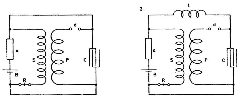
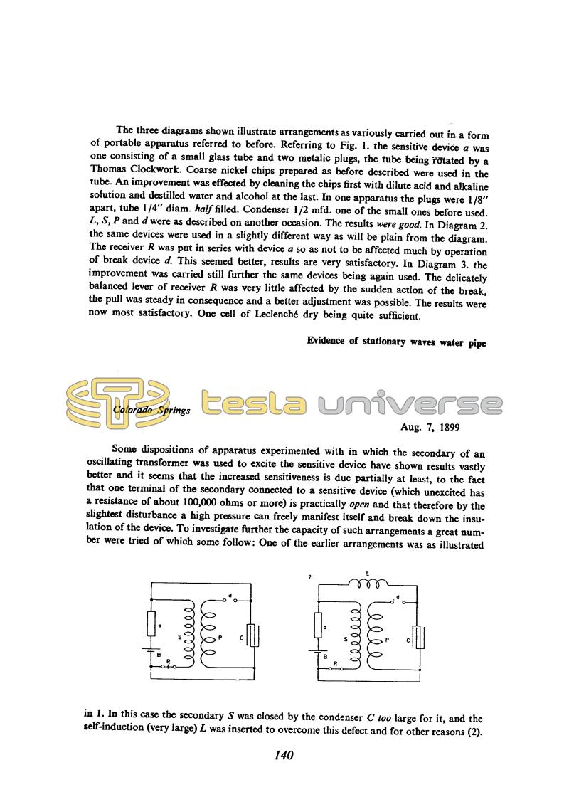
The three diagrams shown illustrate arrangements as variously carried out in a form of portable apparatus referred to before. Referring to Fig. 1. the sensitive device a was one consisting of a small glass tube and two metallic plugs, the tube being rotated by a Thomas Clockwork. Coarse nickel chips prepared as before described were used in the tube. An improvement was effected by cleaning the chips first with dilute acid and alkaline solution and distilled water and alcohol at the last. In one apparatus the plugs were 1/8" apart, tube 1/4" diam. half filled. Condenser 1/2 mfd. one of the small ones before used. L, S, P and d were as described on another occasion. The results were good. In Diagram 2. the same devices were used in a slightly different way as will be plain from the diagram. The receiver R was put in series with device a so as not to be affected much by operation of break device d. This seemed better, results are very satisfactory. In Diagram 3. the improvement was carried still further the same devices being again used. The delicately balanced lever of receiver R was very little affected by the sudden action of the break, the pull was steady in consequence and a better adjustment was possible. The results were now most satisfactory. One cell of Leclenché dry being quite sufficient.
Evidence of stationary waves water pipe
Colorado Springs
Aug. 7, 1899
Some dispositions of apparatus experimented with in which the secondary of an oscillating transformer was used to excite the sensitive device have shown results vastly better and it seems that the increased sensitiveness is due partially at least, to the fact that one terminal of the secondary connected to a sensitive device (which unexcited has a resistance of about 100,000 ohms or more) is practically open and that therefore by the slightest disturbance a high pressure can freely manifest itself and break down the insulation of the device. To investigate further the capacity of such arrangements a great number were tried of which some follow: One of the earlier arrangements was as illustrated
in 1. In this case the secondary S was closed by the condenser C too large for it, and the self-induction (very large) L was inserted to overcome this defect and for other reasons (2).
140


