Nikola Tesla Books
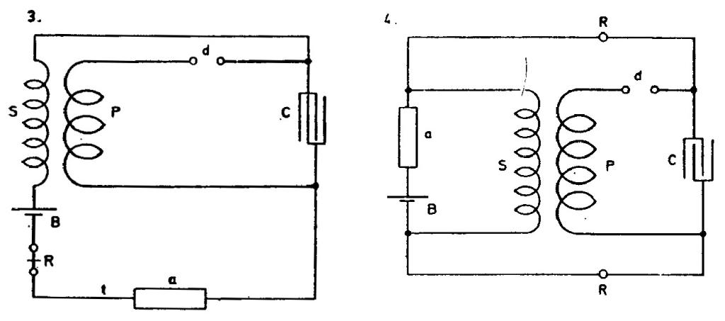
The next arrangement adopted was as shown in 3. In this case the terminal of secondary, or respectively its continuation up to t was open or insulated - at least practically so and the apparatus was more sensitive when the secondary had a great number of turns, it was better to place battery B and receiver R between the other end of secondary and the corresponding terminal of the condenser, but when the secondary did not have as many turns the apparatus generally worked better with battery and relay placed as shown in 3. as
they caused a certain rise - by their capacity and self-induction - of the electrical pressure on terminal t of sensitive device.
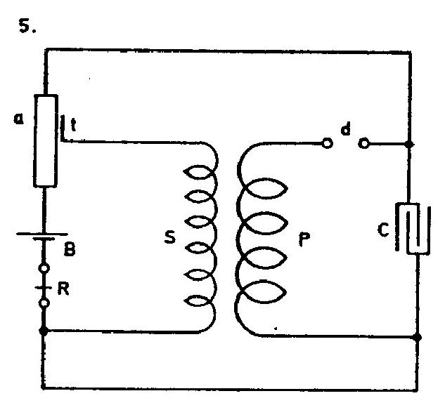
A modification of Fig. 2. is shown in Fig. 4. In this case the self-induction L was replaced by relay R R which had one of its legs or coils inserted in each of the two branches of the circuit leading from the condenser as illustrated. As the relay had a very high winding and high resistance nearly 1000 ohms, this left the secondary practically opened and free to work on sensitive device a.
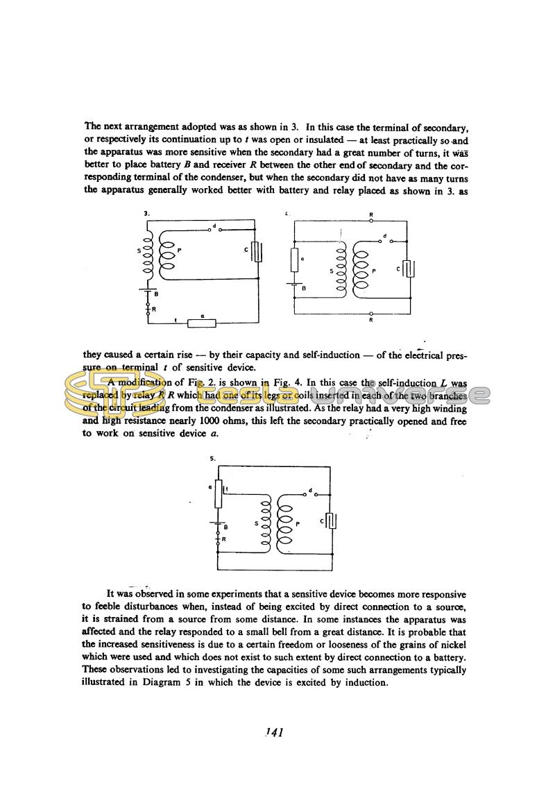
It was observed in some experiments that a sensitive device becomes more responsive to feeble disturbances when, instead of being excited by direct connection to a source, it is strained from a source from some distance. In some instances the apparatus was affected and the relay responded to a small bell from a great distance. It is probable that the increased sensitiveness is due to a certain freedom or looseness of the grains of nickel which were used and which does not exist to such extent by direct connection to a battery. These observations led to investigating the capacities of some such arrangements typically illustrated in Diagram 5 in which the device is excited by induction.
141


