Nikola Tesla Books
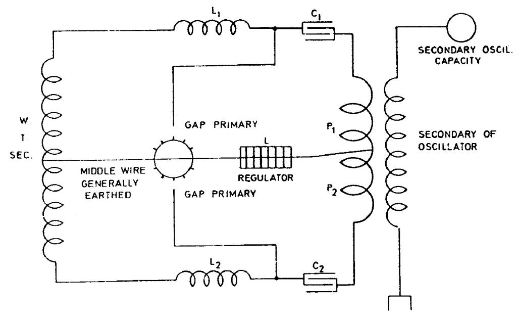
Plan here illustrated seems free of these objections:
Here the short-circuit is avoided by the use of self-inductions L1 and L2 which must be well insulated to stand high tensions. A single self-induction inserted in the middle wire may also be used with like effect.
Colorado Springs
Aug. 18, 1899
The best result with apparatus at command, that is, 3 supply transformers. West. Tr. and condensers newly constructed is obtained by employing two dielectrics giving total capacity of condensers equal to that of four tanks. This allows working with 22,500 volts safely.
The results will probably be the same with 45,000 volts connection and 4 dielectrics but then capacity is only one tank and sparks in primary are longer and more difficult to control.
With connection illustrated before (Diagr. I or II) it is also practicable to work with 45,000 volts total by connecting the tanks on each side in a series so that capacity of each of the two alternately working circuits is equal to that of two tanks. That is 2 x 0.03816 = 0.07632 mfd.
With one primary turn this gives
!$ {T = {{2 \pi \over 10^{3}} \sqrt{0.07632 \times {7 \over 10^{5}}}} = {{2 \pi \over 10^{5}} \sqrt{0.053424}} = {1.4553 \over 10^{5}}} !$
and n = 68,710 adding 10% for mutual induction, now smaller because smaller number of turns in secondary (29), we have
n = {68,7006900} = 75,600 say n = 76,000 and λ = 2.45 miles !$ {λ \over 4} !$ = 3234 feet.
154


