Nikola Tesla Books
In Diagram 1. first experimented with, a disadvantage was found to exist: namely, the receiver R was operated through the break device d. This inconvenience was done away with in arrangement illustrated in Fig. 2. which allowed more sensitive-adjustment of Relay R and the apparatus worked better. Capacity of condenser was varied up to 20 mfd. with changing success. Best results seemingly with small capacities up to 1 mfd. Secondary about 4,000 turns, primary Lamp cord No. 10 turns 28. The apparatus responded freely to small pocket coil at a distance of several feet with no capacity attached and no adjusted circuit. Consequently will go at great distance.
In these arrangements, as in the previous ones involving the same principle, the effect on the sensitive device is accumulative and a difficulty arises that namely the sensitive device will not readily de-sensitive. By inserting large resistance r in circuit with receiver R this effect upon the latter is largely reduced as the current through receiver and device is kept to a minimum. By adjusting speed of rotation of sensitive device the inconvenience is also overcome.
Colorado Springs
Aug. 23, 1899
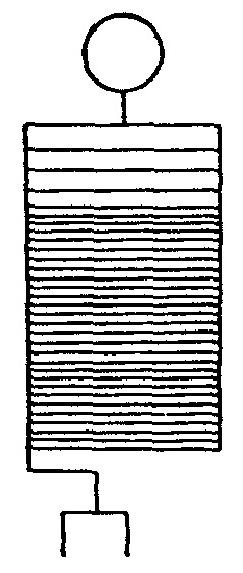
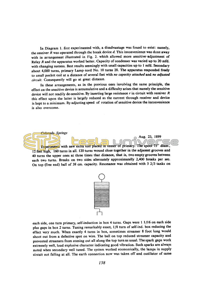
Experiments with new extra coil placed in center of primary. The spool 75" diam., 12 feet high, 160 turns in all. 120 turns wound close together in the adjacent grooves and 40 turns the upper ones at three times that distance, that is, two empty grooves between each two turns. Breaks on two sides alternately approximately 2,400 breaks per sec. On top (free end) ball of 38 cm. capacity. Resonance was obtained with 5 2/3 tanks on each side, one turn primary, self-induction in box 4 turns. Gaps were 1 1/16 on each side plus gaps in box 2 turns. Tuning remarkably exact, 1/8 turn of self-ind. box reducing the effect very much. When exactly 4 turns in box, sometimes streamer 8 foot long would shoot out from a defective spot on wire. The ball on top reduced streamer capacity and prevented streamers from coming out all along the top turn as usual. The spark gaps work extremely well, loud explosive character indicating good vibration. Such sparks are always noted when secondary well tuned. The system worked economically, the lamps in supply circuit not falling at all. The earth connection now was taken off and oscillator of same
158
August 22
In this entry he returns once again to the receivers. He tried out two receiver circuits using one battery and one sensitive device. He changed the capacity in the primary circuit over a wide range, but it is not clear why 1 uF proved best. It remains unexplained what was the relationship between the frequency of the incoming signal and that generated by the receiver itself. Could it perhaps be, if the rotating coherer behaved as a nonlinear element, that the signal was amplified as in a heterodyne receiver(55)?
August 23
He now put the extra coil in the center of the primary, retaining this configuration from then on. After the usual adjustment of the oscillator he got sparks 2 m, and later 4 m long, indicating a voltage of around 2 million volts.


