Nikola Tesla Books
Colorado Springs
Aug. 29, 1899
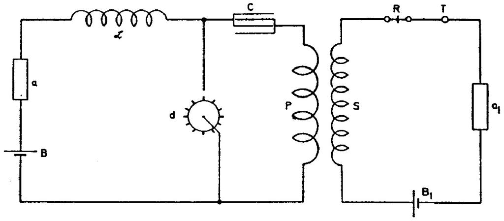
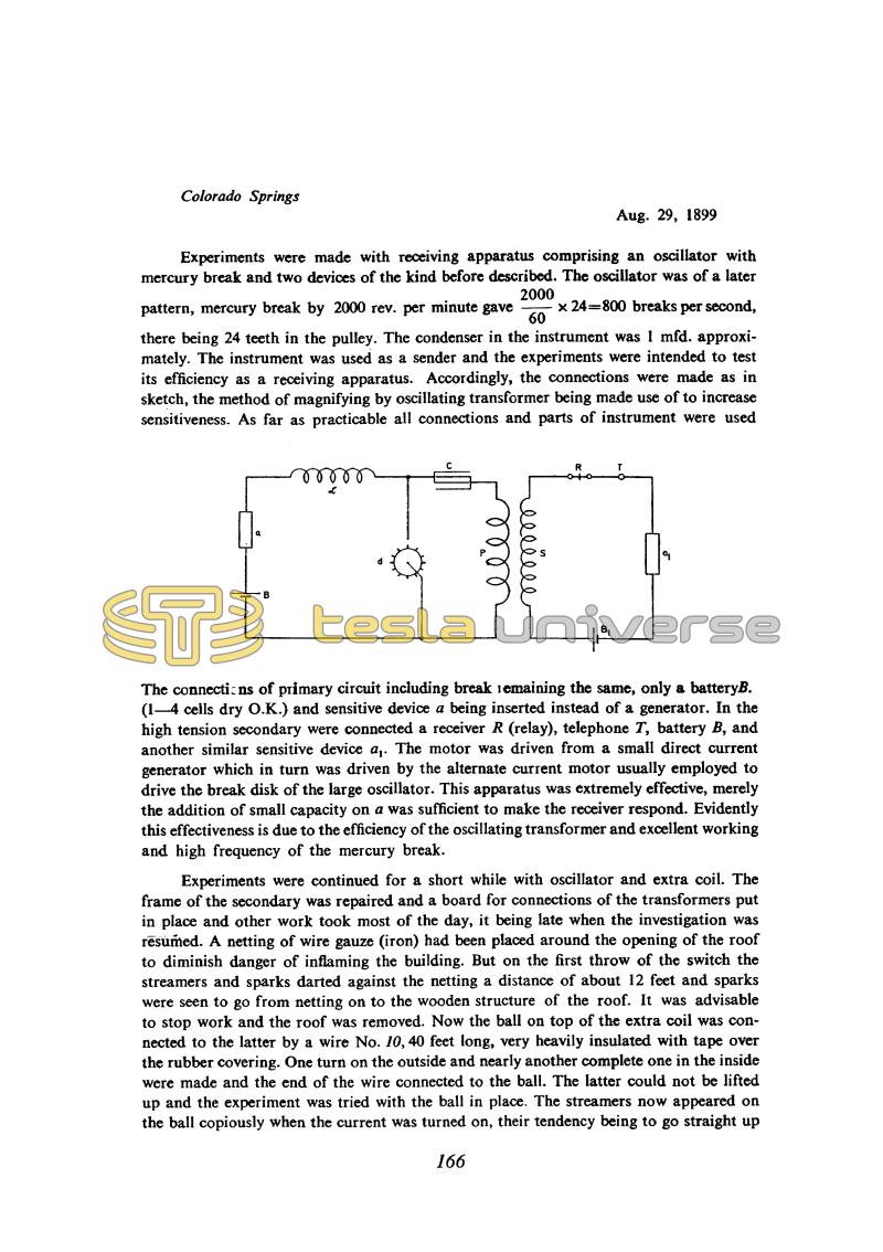
Experiments were made with receiving apparatus comprising an oscillator with mercury break and two devices of the kind before described. The oscillator was of a later pattern, mercury break by 2000 rev. per minute gave !$ {{{2000 \over 60} \times 24} = 800} !$ breaks per second, there being 24 teeth in the pulley. The condenser in the instrument was 1 mfd. approximately. The instrument was used as a sender and the experiments were intended to test its efficiency as a receiving apparatus. Accordingly, the connections were made as in sketch, the method of magnifying by oscillating transformer being made use of to increase sensitiveness. As far as practicable all connections and parts of instrument were used
The connections of primary circuit including break remaining the same, only a battery B. (1 - 4 cells dry O.K.) and sensitive device a being inserted instead of a generator. In the high tension secondary were connected a receiver R (relay), telephone T, battery B, and another similar sensitive device a1. The motor was driven from a small direct current generator which in turn was driven by the alternate current motor usually employed to drive the break disk of the large oscillator. This apparatus was extremely effective, merely the addition of small capacity on a was sufficient to make the receiver respond. Evidently this effectiveness is due to the efficiency of the oscillating transformer and excellent working and high frequency of the mercury break.
Experiments were continued for a short while with oscillator and extra coil. The frame of the secondary was repaired and a board for connections of the transformers put in place and other work took most of the day, it being late when the investigation was resumed. A netting of wire gauze (iron) had been placed around the opening of the roof to diminish danger of inflaming the building. But on the first throw of the switch the streamers and sparks darted against the netting a distance of about 12 feet and sparks were seen to go from netting on to the wooden structure of the roof. It was advisable to stop work and the roof was removed. Now the ball on top of the extra coil was connected to the latter by a wire No. 10, 40 feet long, very heavily insulated with tape over the rubber covering. One turn on the outside and nearly another complete one in the inside were made and the end of the wire connected to the ball. The latter could not be lifted up and the experiment was tried with the ball in place. The streamers now appeared on the ball copiously when the current was turned on, their tendency being to go straight up
166
August 29
Although the circuit looks simple enough, an analysis of Tesla's receiver with a "magnifying effect" is rather complicated, because transient phenomena have to be taken into account and the resistance law of the sensitive devices as a function of voltage has to be known. It was not easy to adjust a receiver like this to work properly.
Apparently there was an earphone T in the secondary circuit of the transformer, but it is not mentioned in the notes. The sensitivity of an earphone would normally be much greater than that of a relay, so it would be interesting to find out how this apparatus performed. Unfortunately, earphones are practically not mentioned anywhere in the diary.
Tesla here at last makes a few remarks about how the sensitivity of receivers was estimated. To test its response he put a "small capacity" across sensitive device a, but of what value, and whether it was charged or not he does not say.
August 29
He describes the receiver with the oscillator and two sensitive devices. This time, instead of a rotating breaker, driven by a clock mechanism, he uses a fast mercury rotating breaker; and instead of circuit elements of the standard receivers, he takes the transmitter circuit. The oscillator transformer serves as excitation amplifier. Tesla's idea of a receiver with an "amplifying effect" could be easily understood by this example. Sensitive device 'a', changes the excitation of oscillator with mercury breaker. This excitation causes the rise of high frequency voltage in the secondary for the higher absolute amount (due to voltage transformation) and therefore the sensitive device 'a1' is more excited than the device 'a' was. Although the circuit appears very simple, the analysis of such a receiver is quite complicated because it is necessary to consider the transient events and to know the losses dictating the changes in sensitive device resistance with supply voltages. It was not easy to adjust such a receiver in order to get it operating correctly.
Tesla put the earphone T in the secondary circuit of the transformer, but in the text he doesn't say anything about it. The earphone sensitivity is normally much higher than the relay sensitivity and therefore it would be interesting to know something about Tesla's experience with this device. Unfortunately, there is no mention in his notes about an earphone.
Finally, Tesla said a little bit about the receiver's sensitivity measurement. In order to check the devices reaction, he puts a small capacitor in parallel with sensitive device 'a'. How big that capacitor is, whether charged or not, he did not say.


