Nikola Tesla Books
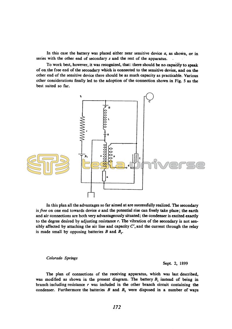
In this case the battery was placed either near sensitive device a, as shown, or in series with the other end of secondary s and the rest of the apparatus.
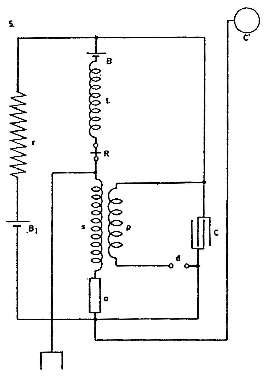
To work best, however, it was recognized, that: there should be no capacity to speak of on the free end of the secondary which is connected to the sensitive device, and on the other end of the sensitive device there should be as much capacity as practicable. Various other considerations finally led to the adoption of the connection shown in Fig. 5 as the best suited so far.
In this plan all the advantages so far aimed at are successfully realized. The secondary is free on one end towards device a and the potential rise can freely take place; the earth and air connections are both very advantageously situated; the condenser is excited exactly to the degree desired by adjusting resistance r. The vibration of the secondary is not sensibly affected by attaching the air line and capacity C', and the current through the relay is made small by opposing batteries B and B1.
Colorado Springs
Sept. 2, 1899
The plan of connections of the receiving apparatus, which was last described, was modified as shown in the present diagram. The battery B1 instead of being in branch including resistance r was included in the other branch circuit containing the condenser. Furthermore the batteries B and B1 were disposed in a number of ways
172
September 1-2
Returning to receiver problems, Tesla begins the analysis of the scheme shown in Fig. 1. With this circuit, he previously achieved good results in view of sensitivity by means of an efficient return link for the purpose of a "high increase of initial excitation''. With regard to series connection of battery and the sensitive device, the pre-excitation created by circuit T - C and which, via secondary S acts on sensitive device is not sufficient. That is why in Fig. 2 one more battery is added, which from this point of view improves the situation, because the pulsating current appears through relay R and therefore the relay in Fig. 3 is relocated to the secondary branch S and the sensitive device. Fig. 4 indicates an even better scheme by which the relay self-inductance influence is reduced by adjusted secondary circuit S.
Fig. 5 shows the best alternative with an aerial which Tesla calls "air line and capacitance" and with grounding by which the electromagnetic field does the excitation of the sensitive device. On September 2 he shows one more scheme and experiments with various voltages of batteries B and B1. He concludes that complete sensitive device excitation is achieved quickly (even at small excitation) if batteries B and B1 are connected so that their influence on capacitor C are added, and that the excitation is interrupted in the case of an opposite battery connection.


