Nikola Tesla Books
Colorado Springs
Sept. 22, 1899
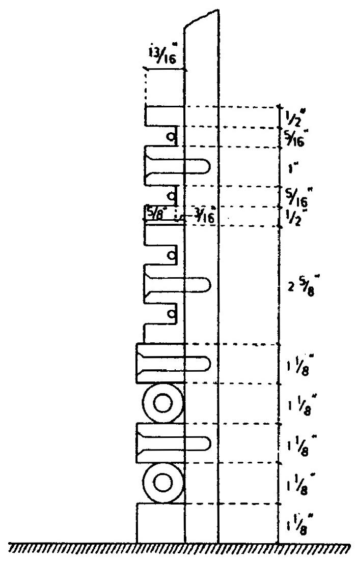
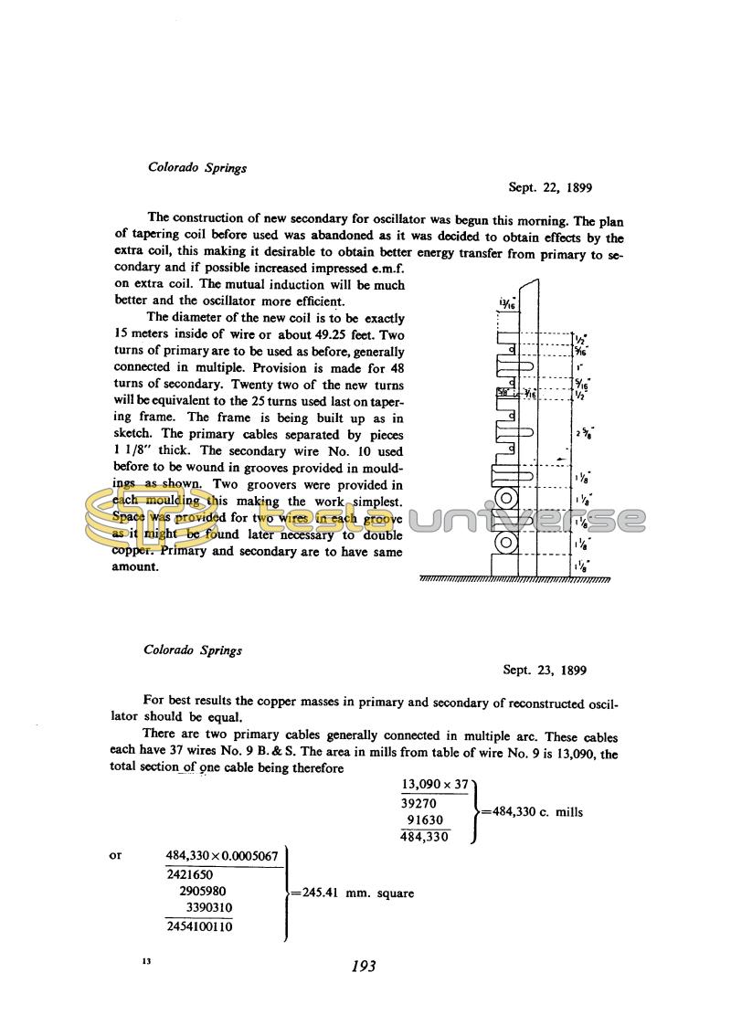
The construction of new secondary for oscillator was begun this morning. The plan of tapering coil before used was abandoned as it was decided to obtain effects by the extra coil, this making it desirable to obtain better energy transfer from primary to secondary and if possible increased impressed e.m.f. on extra coil. The mutual induction will be much better and the oscillator more efficient.
The diameter of the new coil is to be exactly 15 meters inside of wire or about 49.25 feet. Two turns of primary are to be used as before, generally connected in multiple. Provision is made for 48 turns of secondary. Twenty two of the new turns will be equivalent to the 25 turns used last on tapering frame. The frame is being built up as in sketch. The primary cables separated by pieces 1 1/8" thick. The secondary wire No. 10 used before to be wound in grooves provided in mouldings as shown. Two groovers were provided in each moulding this making the work simplest. Space was provided for two wires in each groove as it might be found later necessary to double copper. Primary and secondary are to have same amount
Colorado Springs
Sept. 23, 1899
For best results the copper masses in primary and secondary of reconstructed oscillator should be equal.
There are two primary cables generally connected in multiple arc. These cables each have 37 wires No. 9 B.& S. The area in mills from table of wire No. 9 is 13,090, the total section of one cable being therefore
| 13,090 x 37 39270 91630 484,330 | } | = 484,330 c. mills |
|
or | ||
| 484,330 x 0.0005067 2421650 2905980 3390310 2454100110 | } | = 245.41 mm. square |
193
Tesla N. "System of transmission of electrical energy", U.S. Patent 645 576, March 20, 1900, Appl. Sept. 2, 1897.
September 22-23
Having investigated the tapering secondary Tesla started making a new, 15 m diameter cylindrical secondary. The criterion that the weight of copper in the primary and secondary should be the same follows from the requirement of equal losses in the two windings (losses in the copper). This way of calculating the gauge of the primary and secondary conductors is applied in designing LF transformers, but for HF transformers it only provides a rough guide, for a number of reasons, e.g.: the current ratio may differ considerably from the turns ratio, skin effect is not taken into account, etc.
September 22-23
He begins to work on the construction of a new secondary, cylindrical in shape, 15 meters in diameter. He plans the use of two primary turns in paralleled with up to 48 turns in the secondary. The primary winding he makes from 37 wires - 2.9 mm in diameter and the secondary from one wire 2.6 mm in diameter. (please see Sept. 23)
The condition requiring the copper weight to be the same in the primary and secondary is based on the equal losses requirement in both turns (copper losses). This way of calculating of the primary and secondary conductor cross section is applied in low frequency technique. For the high frequency transformer this has mainly an orientation characteristic. There are many reasons for this. For example, the ratio of primary/secondary current could differ substantially from the rates of their number of turns through skin effect and so on.


