Nikola Tesla Books
The short stout wire was now substituted by each of the two primary turns separately and joined in multiple with the results indicated below:
| !$ {32 \over 2} !$ | 13 1/4 turns+1 primary+connections | The primary used was the upper one. |
| !$ {32 \over 2} !$ | 14 " + 1 " + " | " " lower one. |
| !$ {32 \over 2} !$ | 14 1/2 " + 1 " " + " | The tuning was very sharp in the first two cases, not quite so in the last instance. |
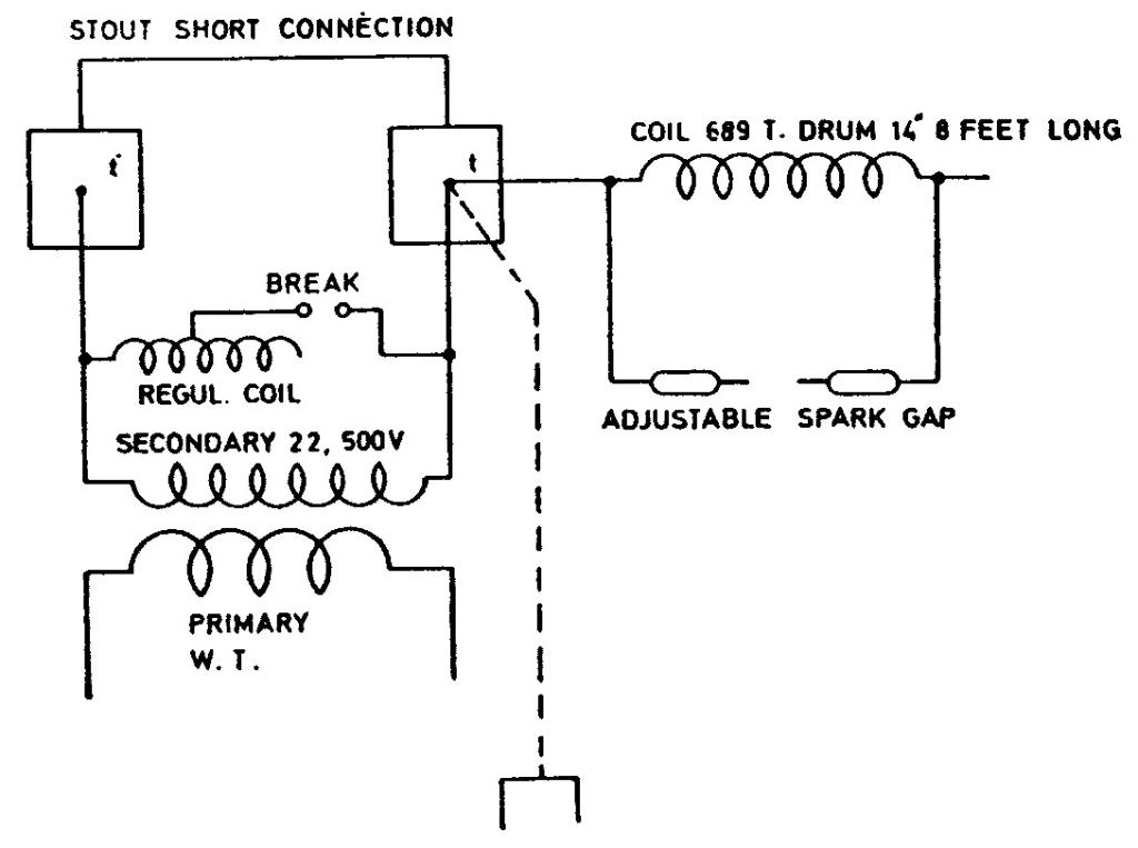
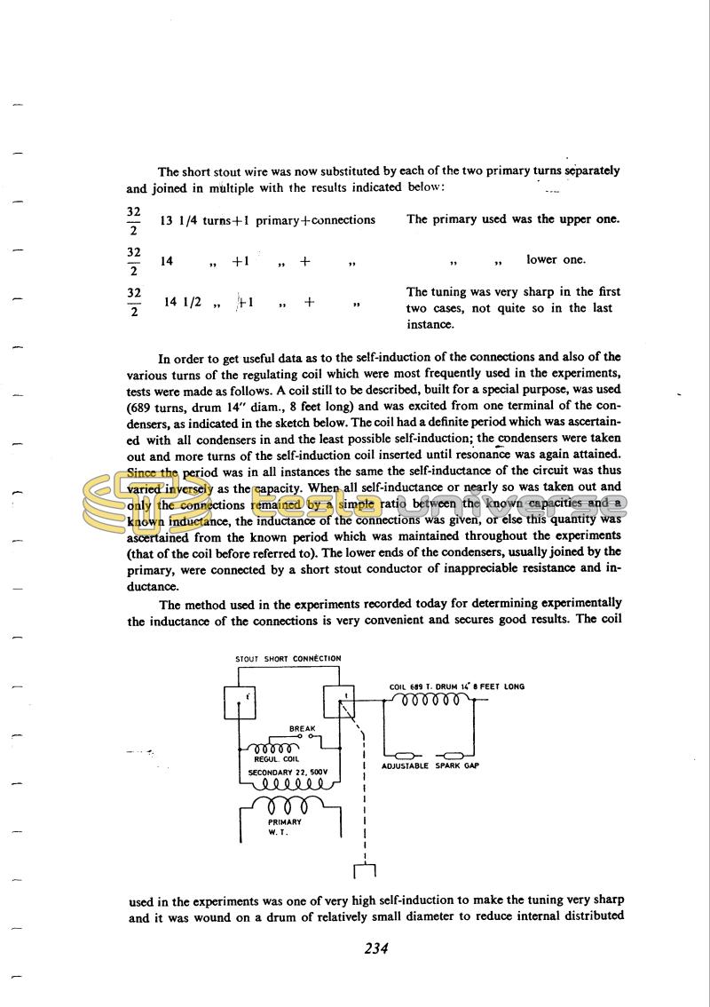
In order to get useful data as to the self-induction of the connections and also of the various turns of the regulating coil which were most frequently used in the experiments, tests were made as follows. A coil still to be described, built for a special purpose, was used (689 turns, drum 14" diam., 8 feet long) and was excited from one terminal of the condensers, as indicated in the sketch below. The coil had a definite period which was ascertained with all condensers in and the least possible self-induction; the condensers were taken out and more turns of the self-induction coil inserted until resonance was again attained. Since the period was in all instances the same the self-inductance of the circuit was thus varied inversely as the capacity. When all self-inductance or nearly so was taken out and only the connections remained by a simple ratio between the known capacities and a known inductance, the inductance of the connections was given, or else this quantity was ascertained from the known period which was maintained throughout the experiments (that of the coil before referred to). The lower ends of the condensers, usually joined by the primary, were connected by a short stout conductor of inappreciable resistance and inductance.
The method used in the experiments recorded today for determining experimentally the inductance of the connections is very convenient and secures good results.
The coil used in the experiments was one of very high self-induction to make the tuning very sharp and it was wound on a drum of relatively small diameter to reduce internal distributed
234
October 22
He applies the same measurement method as on the previous day and finds a number of values for the primary inductance and capacitance (for the purpose of determination of the inductance of the connections). The oscillator's frequency is determined on the basis of a maximum spark at the coil's terminals with 689 turns (please see the figure).
In continuing the measurements he adds a high power transformer primary coil in the oscillator's arcing circuit. He uses only some measurement data for finding the inductance of connections.


