Nikola Tesla Books
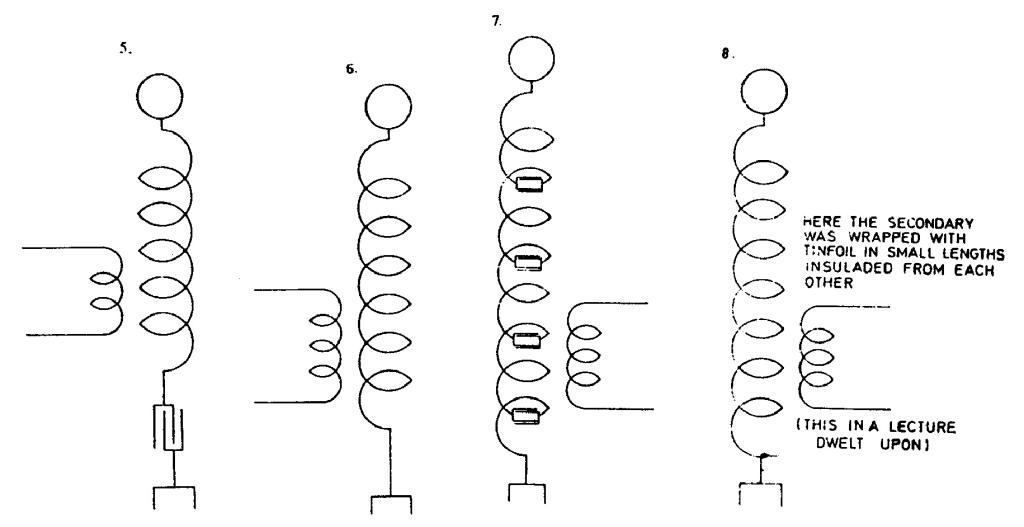
pressure of the secondary were used to shunt the same; in 4. a larger part of secondary inductance was counteracted by a condenser; in 5. the entire secondary inductance was counteracted by a condenser; in 6. the inductance of the secondary was reduced by placing the turns far apart; in 7. inductance was counteracted by a series of condensers inserted between the turns and also distributed capacity was reduced and in 8. (not shown) static screening was resorted to.
Colorado Springs
July 9, 1899
To ascertain to what extent the distributed capacity of secondary wire No. 10 was responsible for the small spark length obtained on the free terminal and to further study this capacity effect, wire No. 31 is to be wound on the secondary frame. For these experiments the present transformer brought from New York is to be used - which can charge just about 16 jars, as now operated, on each side of the primary, this giving primary capacity = 8 jars or 8x0.003=0.024 mfd. Since L with connections (l primary turn) is L = !$ {{7 \times 10^{4}} \over 10^{9}} !$ = !$ {7 \over 10^{5}} !$ henry, the period of the system to be adopted for new experimental coil of this wire will be:
T = !$ {{{2 \pi} \over 10^{3}} \sqrt{{7 \over 10^{5}} \times {24 \over 1000}}} !$ = !$ {{{2 \pi} \over 10^{7}} \sqrt{168}} !$
!$ {\sqrt{168}} !$ = 12.9
68:2
2400:24
159
70
July 8
Detailed consideration of high frequency transformer is actually a resume of obtained experiences and theoretical thoughts. In order to achieve the goal - the machine of higher power and voltage, Tesla looks for methods to optimize all oscillator details; arcing device, primary and secondary inductances, mutual inductance and distributed secondary capacitance. In the analysis he makes the distinction between the device which would be used for high power transmission at a distance, and that one where small power is required as e.g., for transmission of messages. For the first type a high frequency transformer would be made in a similar way as for low frequencies (therefore with a strong link), and for the other type, high secondary voltage would be achieved by the use of over voltage on the secondary circuit which is poorly linked with primary circuits. In the latter case a maximum validity factor pL/R is required and minimal secondary capacitance.
By considering the oscillator operation, Tesla came to one interesting conclusion on the primary coil conductor shape. He discovered that flat cross-section conductor is better than a circular cross-section conductor, because it gets heated less under the same operating conditions. It is considered that there is some reason for that "which hasn't been satisfactorily explained as yet". As the shape of a flat conductor is not known, it is not possible to calculate the reduction factor of conductor resistance in relation to circular conductor resistance of the same cross-section due to skin effect influence.
The area of a flat conductor is always larger than the area of a circular conductor of the same cross-section and length, and the flatter the conductor is, the more that fact is emphasized. For the ratio between width and thickness of conductor of approximately 10, the conductor has approximately 1.8 times larger area, and therefore considerable resistance reduction could occur which is, if not entirely, then at least, a partial explanation of the event which Tesla discovered experimentally.
The problem Tesla frequently turns back to, related to coils, is the question of event propagation speed through the circuit. Tesla considered that in secondary circuits, where the maximum voltage at coil terminals without additional capacitance has to be produced, it is necessary to wind the coil with wire one quarter of wavelength long. This would be quite correct when a straight conductor one quarter of wavelength would be taken and be grounded at one end. When such a system would be excited, at the open end the maximum voltage would be achieved, but its magnitude, at constant excitation, would strongly depend on whether the conductor is horizontal (when radiation is small, and therefore the resonant system with high validity factor would be achieved) or vertical (when system radiates efficiently, and it behaves as a resonant damped system). When a spiral conductor as at Tesla's oscillator was applied, the radiation is very slight as with a horizontal conductor, and therefore the high overvoltages are possible, unless they are reduced by distributed capacitance. Actually, with a spiral conductor the longitudinal inductance and capacitance are increased, and consequently the current propagation speed in the coil is reduced, which requires the shortening of the wire in order to achieve maximum voltage at the coil's terminal. When a capacitive load is added at the end of the coil (e.g., the metal sphere), the coil length has to be shortened even more in order to maintain the resonant conditions in the system. Both these effects Tesla took in account when designing the secondary.
On figures 1-3 several systems are shown, by which the secondary distributed capacitance reduction is achieved. The solution with separated turns is frequently used even today (Fig. 6) when the distributed capacitance influences the circuit operation in which that coil exists.
July 9
In order to check the secondary distributed capacitance influence, Tesla prepares new experiments with secondary coils where considerable reduction of undesirable capacitance could be expected. He performs the operating frequency calculation by a previously established method using inductance and capacitance in the primary circuits. A new secondary is wound by thinner wire (0.23mm in diameter instead of 2.6mm), and parameters of this coil he determines according to normal coil parameters on the same core (for equations explanations, please see June 28) with factor D as parameter. When calculating the factor D (which represents the ratio between turns separation of old and new secondary), the period is exchanged with the number of periods per second by mistake, and instead of having D = 2.45, D = 83. Other numerical errors crept in on other equations from which the relationship between D and C is obtained (the number 38 is omitted under square root) and consequently C obtained was 10,000cm instead of 227 cm. Because these results were not used, it is obvious that Tesla did not want to draw attention to this mistake.
The method by which Tesla measured the oscillator frequency by means of additional (auxiliary) coil is interesting. This coil with its distributed capacitance represented actually an absorbing resonant circuit, and the spark at the coil terminals served as indicator (to a certain extent this circuit is similar to a Hertz resonator). Tesla was adjusting the coil by varying the number of its turns until he obtained the biggest spark at coil terminals.
Then he calculated the oscillations wavelength on the basis of wire length on the coil at an achieved resonance (considering that the wire length in the coil is then equal to one quarter of wavelength. The wire length he finds on the basis of measured wire resistance value and known resistance per unit of length. This method, which in itself, hides the systematic error due to neglecting the speed propagation reduction through the coil(45), is applicable for oscillators of larger power. In Tesla's present experiments this is the most reliable method for determining the oscillations' frequencies.
In the calculations method of determining the oscillation period, Tesla applies two equations: one in which he neglects the secondary influence (as e.g., the beginning of note July 9) and the other, when he takes into account the secondary influence. In the latter case he considers that the primary inductance is reduced by a ratio 1 - M2/NL, which corresponds to a primary inductance reduction when the secondary is short circuited. How much of this is correct, it is difficult to estimate, because the oscillator with intensive discharge does not follow the simple theory of an oscillator with a resonant transformer. Secondary circuit is then considerably damped, and free oscillations in secondary quickly disappear, and therefore it would be necessary to apply a theory which takes into account oscillations of a high damped level.
The same day Tesla returns to a problem of approximate distributed capacitance calculations. This time he applies the Kelvin equation for determining the capacitance of a co-axial conductor. He considers that the outside conductor consists of two adjacent turns so that the capacitance calculated for the co-axial conductor reduces the ratio of wire radius and distance between two coil turns. Although not proving the applicability of such approach (e.g., how this equation could be applied in the case when two turns are around a middle turn shown in Fig. 2 at different potential) he calculates the coil total distributed capacitance and obtains a value which he says matches the measured one. The capacitance so determined is not equal to the ideal coil capacitance, which is shown in an equivalent coil schematic in parallel with a pure inductance.


