Nikola Tesla Books
Now the capacity in the primary circuit was ten new jars on each side, this making a five jars total or 5 x 0.0025 = 0.0125 mfd. or !$ {125 \over 10^{4}} !$ mfd. From this the period of the system ought to have been
!$ {2 \pi \over 10^{3}} \sqrt{{125 \over 10^{4}} L \left(1 -{M^{2} \over NL}\right)} !$ N = inductance of secondaryL = inductance of primaryM = mutual inductance
But on a previous occasion 1 - !$ {M^{2} \over NL} !$ was found to be nearly 0.6 so that
T = !$ {{2 \pi \over 10^{3}} \sqrt{{125 \over 10^{4}} \times 0.6 \times L}} !$ Taking now L = 7 x 104 cm. or !$ {7 \over 10^{5}} !$ henry we have
!$ {T = {2 \pi \over 10^{3}}{\sqrt{{125 \over 10^{4}} \times {6 \over 10} \times {7 \over 10^{5}}}} = {2 \pi \over 10^{8}} {\sqrt{42 \times 125}} =} !$
!$ {= {{2 \pi \over 10^{3}}}{\sqrt{5250}} = {{72.46 \times 2 \pi} \over 10^{8}} = {455 \over 10^{8}}} !$ approx.
and from this would follow n1 = !$ {10^{8} \over 455} !$ = 219,800 per second. This is fairly close within the limits of ordinary errors of measurement and observation.
On the bases of above estimate of n, we may also determine the inductance of primary cables or cable as modified by the influence of the secondary since we have the equation
!$ {1 \over 215,370} !$ = !$ {2 \pi \over 10^{3}} {\sqrt{{125 \over 10^{4}}L'}} !$ which gives !$ L' = {{\left(10^{4} \over {21,537 \times 2 \pi}\right)^{2}} \times {1 \over 125} = {10^{8} \over {185,537 \times 10^{5}}} \times {1 \over 125}} !$
!$ {L' = {10^{8} \over {2319 \times 10^{4} \times 10^{5}}} = {1 \over 23,190}} !$ henry or !$ {{10^{9} \over 23,190} = {10^{8} \over 2319}} = !$ 43,120 cm.
This is not far from the truth since
7 x 104 x 0.6 = 70,000 x 0.6 = 42,000 cm.
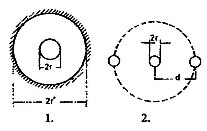
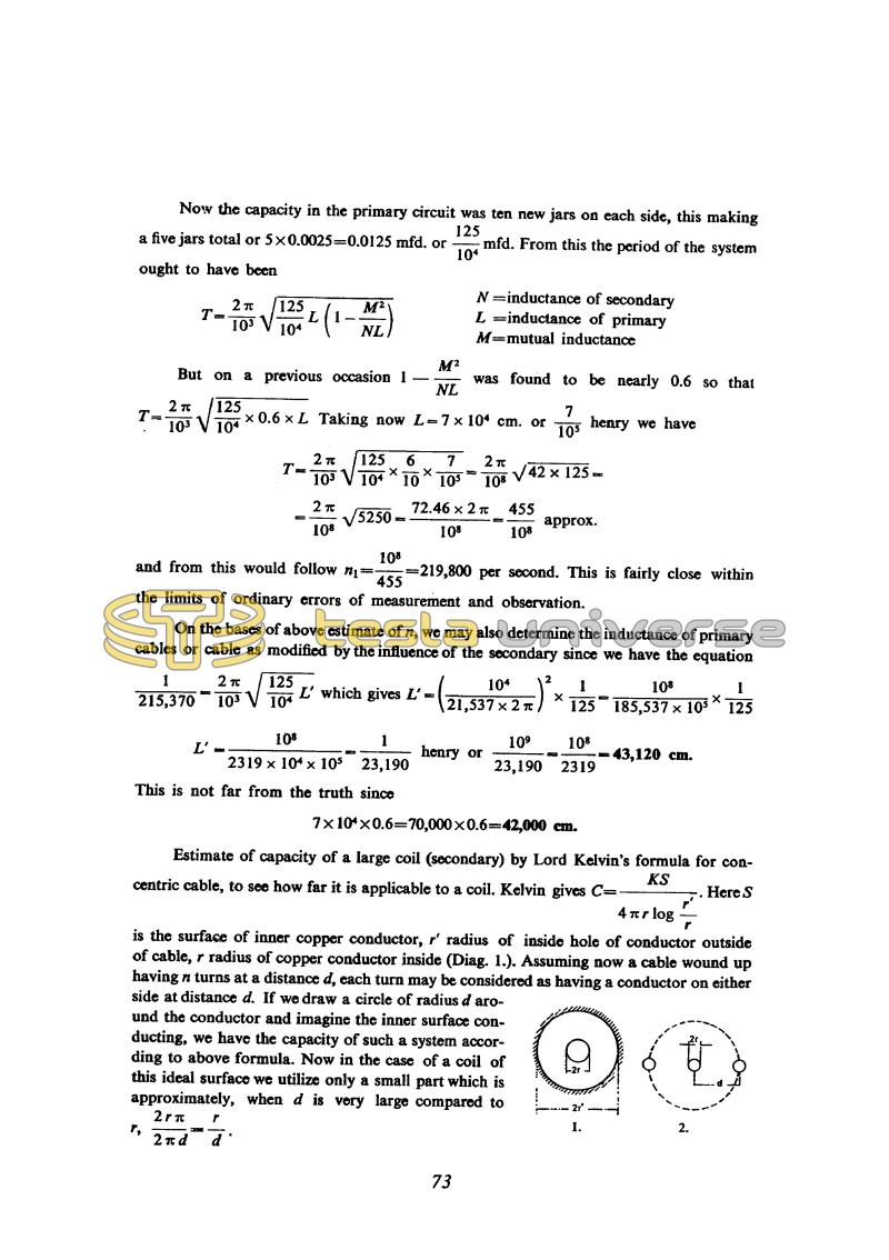
Estimate of capacity of a large coil (secondary) by Lord Kelvin's formula for concentric cable, to see how far it is applicable to a coil. Kelvin gives C = !$ {{KS \over {4 \pi r \log {r' \over r}}}} !$. Here S is the surface of inner copper conductor, r' radius of inside hole of conductor outside of cable, r radius of copper conductor inside (Diag. 1.). Assuming now a cable wound up having n turns at a distance d, each turn may be considered as having a conductor on either side at distance d. If we draw a circle of radius d around the conductor and imagine the inner surface conducting, we have the capacity of such a system according to above formula. Now in the case of a coil of this ideal surface we utilize only a small part which is approximately, when d is very large compared to r, !$ {{2 r \pi \over 2 \pi d} = {r \over d}} !$.
73
July 9
In order to check the secondary distributed capacitance influence, Tesla prepares new experiments with secondary coils where considerable reduction of undesirable capacitance could be expected. He performs the operating frequency calculation by a previously established method using inductance and capacitance in the primary circuits. A new secondary is wound by thinner wire (0.23mm in diameter instead of 2.6mm), and parameters of this coil he determines according to normal coil parameters on the same core (for equations explanations, please see June 28) with factor D as parameter. When calculating the factor D (which represents the ratio between turns separation of old and new secondary), the period is exchanged with the number of periods per second by mistake, and instead of having D = 2.45, D = 83. Other numerical errors crept in on other equations from which the relationship between D and C is obtained (the number 38 is omitted under square root) and consequently C obtained was 10,000cm instead of 227 cm. Because these results were not used, it is obvious that Tesla did not want to draw attention to this mistake.
The method by which Tesla measured the oscillator frequency by means of additional (auxiliary) coil is interesting. This coil with its distributed capacitance represented actually an absorbing resonant circuit, and the spark at the coil terminals served as indicator (to a certain extent this circuit is similar to a Hertz resonator). Tesla was adjusting the coil by varying the number of its turns until he obtained the biggest spark at coil terminals.
Then he calculated the oscillations wavelength on the basis of wire length on the coil at an achieved resonance (considering that the wire length in the coil is then equal to one quarter of wavelength. The wire length he finds on the basis of measured wire resistance value and known resistance per unit of length. This method, which in itself, hides the systematic error due to neglecting the speed propagation reduction through the coil(45), is applicable for oscillators of larger power. In Tesla's present experiments this is the most reliable method for determining the oscillations' frequencies.
In the calculations method of determining the oscillation period, Tesla applies two equations: one in which he neglects the secondary influence (as e.g., the beginning of note July 9) and the other, when he takes into account the secondary influence. In the latter case he considers that the primary inductance is reduced by a ratio 1 - M2/NL, which corresponds to a primary inductance reduction when the secondary is short circuited. How much of this is correct, it is difficult to estimate, because the oscillator with intensive discharge does not follow the simple theory of an oscillator with a resonant transformer. Secondary circuit is then considerably damped, and free oscillations in secondary quickly disappear, and therefore it would be necessary to apply a theory which takes into account oscillations of a high damped level.
The same day Tesla returns to a problem of approximate distributed capacitance calculations. This time he applies the Kelvin equation for determining the capacitance of a co-axial conductor. He considers that the outside conductor consists of two adjacent turns so that the capacitance calculated for the co-axial conductor reduces the ratio of wire radius and distance between two coil turns. Although not proving the applicability of such approach (e.g., how this equation could be applied in the case when two turns are around a middle turn shown in Fig. 2 at different potential) he calculates the coil total distributed capacitance and obtains a value which he says matches the measured one. The capacitance so determined is not equal to the ideal coil capacitance, which is shown in an equivalent coil schematic in parallel with a pure inductance.


