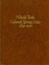
Nikola Tesla Books
Books written by or about Nikola Tesla

ohms approx. To get a rough idea of how the coil might work suppose that on the primary there would be 40,000 volts and that there were 36 turns of secondary, then there would be theoretically an e.m.f. on the terminals of secondary 40,000 x 36 = 1,440,000 volts and, deducting with reference to mutual inductance 40%, we would have 1,444,000 x 0.6 = 864,000 volts impressed or induced e.m.f. Suppose now we had a capacity of 480 cm. on the free terminal as before estimated, the charge stored in this condenser would be: Coulombs or amp. - sec. }: !$ {{864,000 \times 480} \over {9 \times 10^{11}}} !$ per one charge and there being 43,500 x 2 = 87,000 charges per second and taking a theoretical case we would have !$ {{864,000 \times 480 \times 87,000} \over {9 \times 10^{11}}} !$ = !$ {{86 \times 87 \times 48} \over {9 \times 10^{4}}} !$ = 4 amp. nearly. The current in the secondary would be quite large for the small section of the wire. Suppose 50 H.P., expended we may say roughly: Esis= 50 x 750 = 37,500 watts. With the above pressure we would have: 864,000 x is = 37,500 or is = 0.043 amp. only. In this case the energy lost per second would be !$ {544 \times {43^{2} \over 10^{6}}} !$ = !$ {{1849 \times 544} \over 10^{6}} !$ = 1 watt approx. The loss in this case, in spite of the great amount of energy transformed, would be ridiculously small owing to the great e.m.f. despite comparatively high resistance of the secondary. But this only seems so, for 544 ohms would be extremely small resistance for such e.m.f. The theoretical case above considered is hardly realizable, it would require an immense amount of energy.
Additional coil used before in some experiments, also in trials with a secondary of No. 31 wire.
Approximate inductance of coil
Data: diam. 2 feet = 24" = 61 cm. = d
Area = !$ {{\pi \over 4} d^{2}} !$ = !$ {{\pi \over 4} \times 3721} !$ = 2922 sq. cm.
length 71" = 71 x 2.54 = approx. 180 cm.
From this L = !$ {{4 \pi N^{2} A} \over 1} !$ = !$ {12.57 \times {{260^{2} \times 2922} \over 180}} !$ N = 260 turns, this gives
L = 13,925,000 cm. approx. = 0.0139 H
Period of primary was before found !$ {1 \over {16 \times 10^{4}}} !$, hence
!$ {{1 \over {16 \times 10^{4}}} = {2 \pi \over 10^{3}} \sqrt{{13,900,000 \over 10^{9}} C}} !$
77
July 10-11
In order to try and increase the secondary voltage of the HF transformer by keeping down the distributed capacity of the secondary Tesla added a third oscillatory circuit, thus obtaining an oscillator with three resonant circuits of which two are tightly coupled*. The third circuit will not necessarily be most strongly excited when its resonant frequency coincides with that of the primary and secondary (assuming these are the same) and the primary and secondary are tightly coupled. If the spark in the primary circuit lasts long, then the tightly coupled primary-secondary system will produce two distinct oscillations, and the third circuit will be most strongly excited if it is tuned to one (strictly speaking to near one) of these two frequencies. On the other hand, if the spark is of short duration the tightly coupled system may oscillate strongest at the resonant frequency of the secondary, and then the third circuit will be excited the strongest when all three have the same resonant frequency. Tesla believed that his system of coupled circuits was producing a single vibration, which under certain conditions is in fact feasible.
July 10
In distributed capacitance, Tesla sees the main obstacle which limits the voltage in the secondary. His assumption regarding the influence of such capacitance he checks now by calculation of a coil model with evenly distributed voltage and capacitances between windings. In order to calculate the active power (for purpose of simplification) he assumes that all energy received by "capacitors" (they represent distributed capacitance) during one quarter period is used up in the second quarter of a period, and so on. In the second half-period, the event is similar, but only the charging is in opposite direction. He thinks that the number of charges (and discharges) is equal to double the number of high frequency current periods.
After mentioning the damaging effect of distributed capacitance, he continues the description of his thoughts on a secondary with thin wire on the same day. He estimates that the induced secondary voltage will be approximately 40% smaller than the ratio between primary and secondary windings, which corresponds to the induced voltage in an open secondary. In our case, however, a current in the secondary circuit will appear which influences the current in the primary, and therefore the induced voltage will have another value.
By adjusting the capacitance in the primary and secondary circuits, he achieves the maximum secondary voltage. How well Tesla knows the physics of the process could be based on the fact that he doesn't lose sight of the influence of the secondary validity factor, and the magnitude of the primary capacitance which determines the amount of power which the source could provide to the oscillator for conversion into high frequency current.
The voltage increase in the secondary, he achieves by addition of a coil with 260 turns wound with wire 2.6mm in diameter. By addition of this coil the oscillator becomes a system with three oscillating circuits, of which two are well linked*. The third circuit does not have to be the most excited, through a strong link with the primary and secondary circuits, when the resonant frequency of the third circuit is matched with the resonant frequencies of primary and secondary circuits (assuming that both of them are the same). If a spark in the primary circuit lasts for a long time (please see app. Fig., 2P-a) then strongly linked system primary-secondary will produce two emphasized oscillations, and the third circuit will be the most excited if it is adjusted on one of two oscillations (strictly taken in vicinity of one of them). If however, the spark in the primary is of short duration, it could happen that with a strong link, the strongly linked system oscillates the most on its own secondary resonant frequency, and consequently then the third circuit would be the most excited when all three circuits are on the same resonant frequency. Tesla assumes that his linked circuits system produces one vibration, and that is under certain conditions achievable if under the term "one" the most emphasized vibration is understood.
For determination of additional coil inductance, he applies the equation for an indefinitely long coil. The coil's self-capacitance he estimates on the basis of known coil resonant frequency, by assuming that it is equal to the reciprocal period value of the primary circuit which he finds from inductance and capacitance of the primary circuit. When with all the calculation of the additional coil validity factor he makes approximations, because he neglects the coil resistance increase with frequency and consequently he gets an unproportionally high validity factor.
* Similar systems were analyzed in 1906 and 1907 by M. Wien, 1907 by C. Fischer and in 1909 by J. Kaiser(46). From these works it can be seen that the effective value of current in a poorly linked circuit will be at maximum if the resonant frequency of this circuit is the same as the other two better linked circuits only when their link is poor.
