Nikola Tesla Books
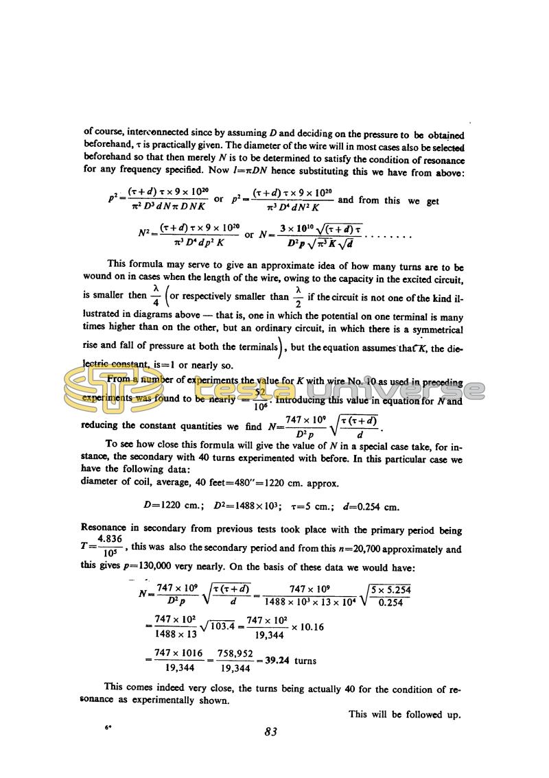
of course, interconnected since by assuming D and deciding on the pressure to be obtained beforehand, Ï is practically given. The diameter of the wire will in most cases also be selected beforehand so that then merely N is to be determined to satisfy the condition of resonance for any frequency specified. Now l = â¼DN hence substituting this we have from above:
This formula may serve to give an approximate idea of how many turns are to be wound on in cases when the length of the wire, owing to the capacity in the excited circuit, is smaller then !$ {λ \over 4} !$ (or respectively smaller than !$ {λ \over 2} !$ if the circuit is not one of the kind illustrated in diagrams above - that is, one in which the potential on one terminal is many times higher than on the other, but an ordinary circuit, in which there is a symmetrical rise and fall of pressure at both the terminals), but the equation assumes that K, the dielectric constant, is = 1 or nearly so.
From a number of experiments the value for K with wire No. 10 as used in preceding experiments was found to be nearly = !$ {52 \over 10^{6}} !$. Introducing this value in equation for N and reducing the constant quantities we find !$ {N = {{747 \times 10^{9}} \over {D^{2} p}} \sqrt{{Ï(Ï + d)} \over d}} !$.
To see how close this formula will give the value of N in a special case take, for instance, the secondary with 40 turns experimented with before. In this particular case we have the following data:
diameter of coil, average, 40 feet = 480" = 1220 cm. approx.
D = 1220 cm.; D2 = 1488 x 103; Ï = 5 cm.; d = 0.254 cm.
Resonance in secondary from previous tests took place with the primary period being !$ {T = {4.836 \over 10^{5}}} !$, this was also the secondary period and from this n = 20,700 approximately and this gives p = 130,000 very nearly. On the basis of these data we would have:
!$ {N = {{{747 \times 10^{9}} \over {D^{2} p}} \sqrt{{Ï(Ï+d)} \over d}} = {{{747 \times 10^{9}} \over {1488 \times 10^{3} \times 13 \times 10^{4}}} \sqrt{{5 \times 5.254} \over 0.254}}} !$
!$ {= {{{747 \times 10^{2}} \over {1488 \times 13}} \sqrt{103.4}} = {{744 \times 10^{2}} \over 19,344} \times 10.16} !$
!$ {= {{747 \times 1016} \over 19,344} = {758,952 \over 19,344} =} !$ 39.24 turns
This comes indeed very close, the turns being actually 40 for the condition of resonance as experimentally shown.
This will be followed up.
6*
83
Tesla: "On light and other high frequency phenomena", a lecture delivered before the Franklin Ins. Philadelphia, Febr. 1893, L-107.
July 11
By introducing the additional coil in the oscillator circuit Tesla achieved one modification of his oscillator with resonant transformer. by which means he obtained higher voltages. When these voltages exceeded several hundred thousand volts, he had to carefully lay out the elements, and choose very good insulators. Here the instructions are given how to make the terminals in order to obtain longest and most powerful spark along with delaying the flashover to the instant when maximum voltage is reached (or some desired voltage). He suggests the procedure which enables the voltage measurement by means of metal spheres of various radii. He discusses the disadvantages of this method because the spheres introduce additional capacitance which disturbs the resonance conditions in high frequency circuits.
Tesla considers the additional coil extraordinarily suitable for the achievement of "any" voltage. He gives two wiring schematics of this coil for an oscillator high frequency transformer. He claims that with this coil. considerably higher voltages are achieved than with the secondary in poorer linkage with the primary.
Tesla explains this with the fact that the additional coil is not in an inductive link with the primary, and there is no such reaction in the primary which would dampen the oscillation. He doesn't explain how he imagines this coil to be excited and not to react on the primary transformer secondary to which it is directly connected.
The additional coil description is very detailed. Tesla's wealthy experience in coil design is obvious in its full extent. At the end of his considerations he gives the equation for determination of the number of turns for the additional coil on the basis of operation frequency, wire diameter, separation of windings, and a constant which he determines on the basis of experimental results. He checks the equation on one example and obtains a result very close to the experimental results.

