Nikola Tesla Books
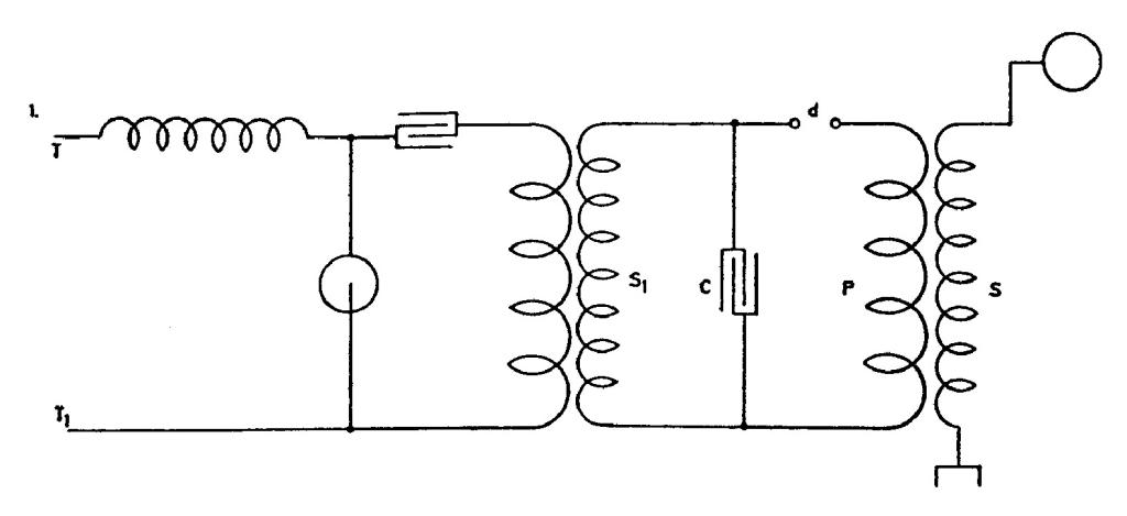
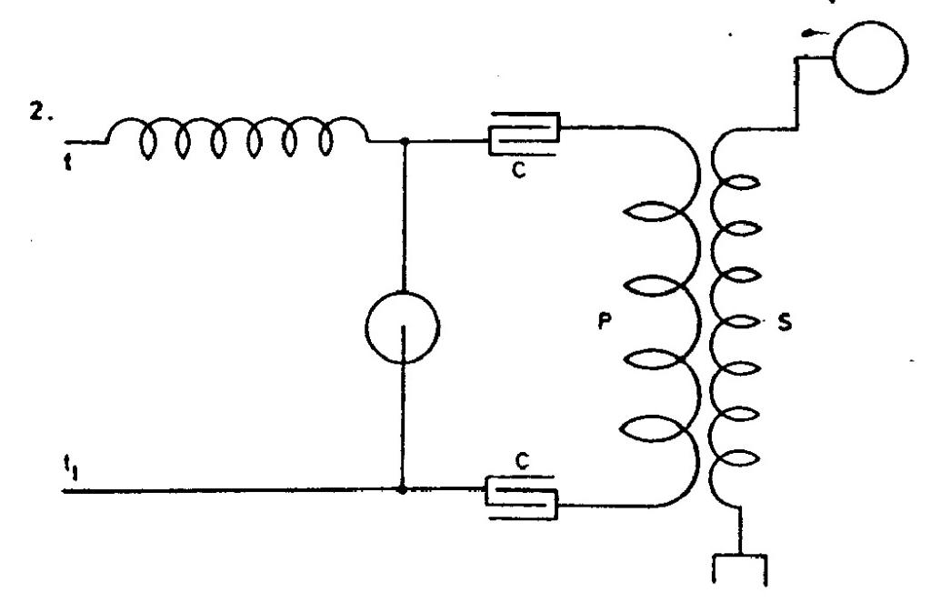
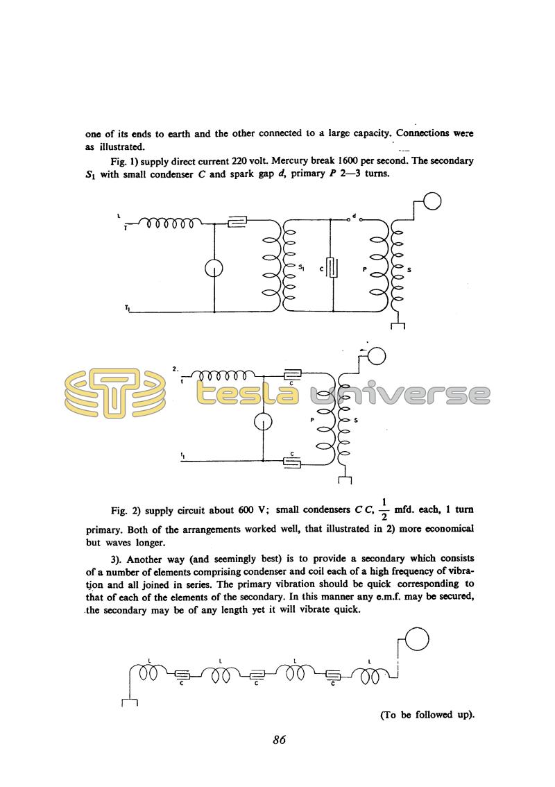
one of its ends to earth and the other connected to a large capacity. Connections were as illustrated.
Fig. 1) supply direct current 220 volt. Mercury break 1600 per second. The secondary S1 with small condenser C and spark gap d, primary P 2 - 3 turns.
Fig. 2) supply circuit about 600 V; small condensers C C, !$ {1 \over 2} !$ mfd. each, 1 turn primary. Both of the arrangements worked well, that illustrated in 2) more economical but waves longer.
3). Another way (and seemingly best) is to provide a secondary which consists of a number of elements comprising condenser and coil each of a high frequency of vibration and all joined in series. The primary vibration should be quick corresponding to that of each of the elements of the secondary. In this manner any e.m.f. may be secured, the secondary may be of any length yet it will vibrate quick.
(To be followed up).
86
July 14
He had tried out the devices shown in these drawings earlier on, some of them for wireless remote control of a boat. Patent No. 613809, "Method of and apparatus for controlling mechanism of moving vessels or vehicles" of 8 November 1898 (application field 1 July 1898) mentions the possibility of using electromagnetic resonance but does not give the circuit diagram of the transmitter referred to here.
July 14
These schematics which he provides, he already tested previously, some of them for wireless boat controls at a distance.* The circuit of figure no , l is a "cascade" oscillator. The mercury breaker enables the production of impulses through the coil of first transformer (S1) which charges the capacitor C, and further is Tesla's classic schematic of a resonant transformer with an arcing device D1. The circuit on Figure 2 shows one of Tesla's oscillator variations which is planned for operations with a direct current source supply.
The oscillator of this type is supplied via ballast coil which prevents the source short circuiting via breaker when it is closed and serves the purpose of source energy accumulation. The capacitors are oscillatingly discharged through the closed breaker producing the high frequency current. When the breaker is open, the oscillations in primary circuit stop, capacitors are again charged from the source and accumulated energy in ballast coil. In these instances, the secondary oscillates as dictated by its inductance and capacitance. This circuit in Figure 3 is supposed to enable the use of a long wire in the secondary, when high frequencies are obtained which correspond to LC circuit vibrations. It is not clear how Tesla imagined that by this method, the electromotive forces of any value could be achieved.
* Please see patent No. 612,809 of November 8, 1898, submitted on July 1, 1898(59). In this patent the possibility of electromagnetic resonance use is mentioned, but the transmitter circuit was not given.


