Nikola Tesla Books
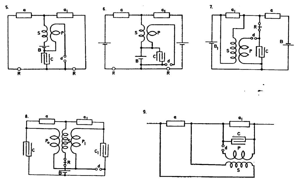
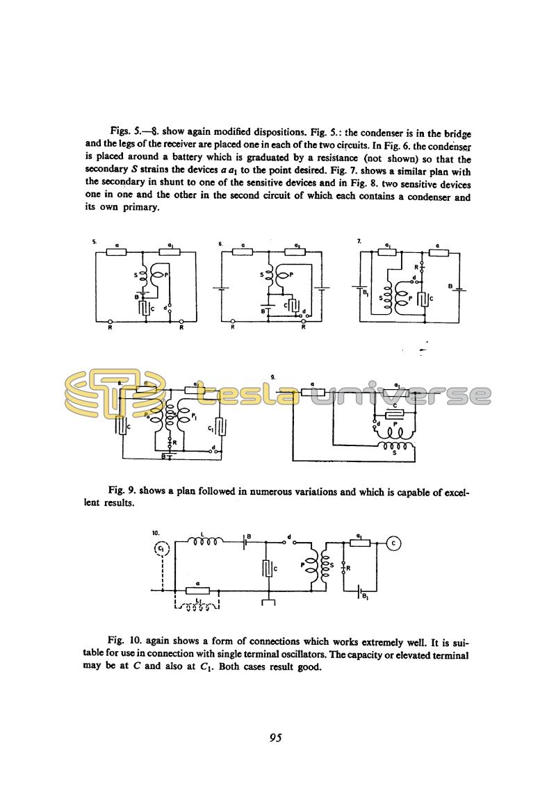
Figs. 5. - 8. show again modified dispositions. Fig. 5.: the condenser is in the bridge and the legs of the receiver are placed one in each of the two circuits. In Fig. 6. the condenser is placed around a battery which is graduated by a resistance (not shown) so that the secondary S strains the devices a a1 to the point desired. Fig. 7. shows a similar plan with the secondary in shunt to one of the sensitive devices and in Fig. 8. two sensitive devices one in one and the other in the second circuit of which each contains a condenser and its own primary.
Fig. 9. shows a plan followed in numerous variations and which is capable of excellent results.
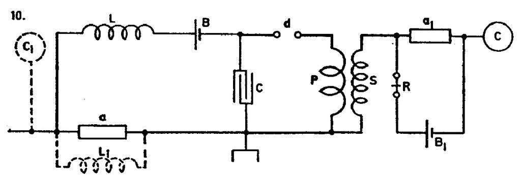
Fig. 10. again shows a form of connections which works extremely well. It is suitable for use in connection with single terminal oscillators. The capacity or elevated terminal may be at C and also at C1. Both cases result good.
95
July 21
In this setup a small excitation of one sensitive device is rapidly amplified by a feedback loop which acts via a transformer on the other sensitive device. Figure 10 shows how the receiver was excited by aerial (elevated metal ball C or C1) - earth system.
July 21
In continuation of work on receivers for continuous high frequency currents, he widens the researches on assemblies with two sensitive devices. He lays the sensitive devices out so that they are sensitive to impulses of one direction, which enables the alternating current commutation. On Fig. 1 and 2, relay coils are connected, so that the actions through both sensitive devices are added together. For other connections a small excitation of the sensitive device is quickly amplified, due to the action of the return link, which acts via the transformer. In Fig. 10, it can be seen how the receiver is excited by means of antenna systems (elevated metal sphere C or C1) - ground.


