Nikola Tesla Books
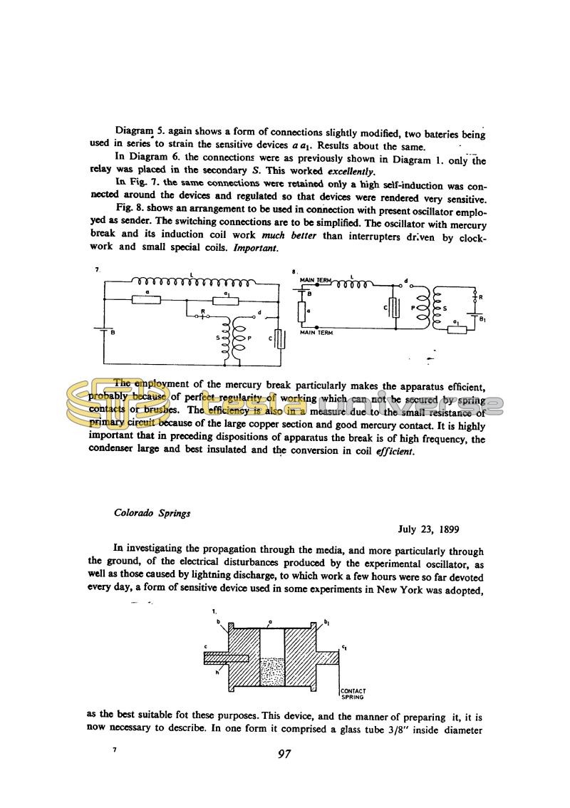
Diagram 5. again shows a form of connections slightly modified, two batteries being used in series to strain the sensitive devices a a1. Results about the same.
In Diagram 6. the connections were as previously shown in Diagram 1. only the relay was placed in the secondary S. This worked excellently.
In Fig. 7. the same connections were retained only a high self-induction was connected around the devices and regulated so that devices were rendered very sensitive.
Fig. 8. shows an arrangement to be used in connection with present oscillator employed as sender. The switching connections are to be simplified. The oscillator with mercury break and its induction coil work much better than interrupters driven by clock work and small special coils. Important.
The employment of the mercury break particularly makes the apparatus efficient, probably because of perfect regularity of working which can not be secured by spring contacts or brushes. The efficiency is also in a measure due to the small resistance of primary circuit because of the large copper section and good mercury contact. It is highly important that in preceding dispositions of apparatus the break is of high frequency, the condenser large and best insulated and the conversion in coil efficient.
Colorado Springs
July 23, 1899
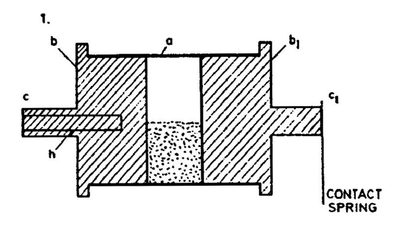
In investigating the propagation through the media, and more particularly through the ground, of the electrical disturbances produced by the experimental oscillator, as well as those caused by lightning discharge, to which work a few hours were so far devoted every day, a form of sensitive device used in some experiments in New York was adopted, as the best suitable for these purposes.
This device, and the manner of preparing it, it is now necessary to describe. In one form it comprised a glass tube 3/8" inside diameter
97
July 22
Figure 8 shows the circuit of a receiver obtained by modification of the transmitter Tesla was then experimenting with. When functioning as a transmitter it is powered from the mains and is in fact a standard Tesla oscillator with a mercury interrupter between the condenser C and the primary P. The relay, sensitive device a1 and battery B1 are omitted and the secondary is connected to the antenna and ground. It may be noted that Tesla did not use the best receiver modification (as in Fig. 6), probably to simplify reconnection as a transmitter.
July 22
With the same elements as on the previous day he continues the experiments witli the receiver. He looks for merthods to reduce the resistance for currents through sensitive devices, and to increase the operation regularity. In Fig. 4, he introduces the schematic in the shape of a bridge with battery, relay and transformer secondary in the diagonal Fig. 8 represents the receiver schematic which is obtained by connecting the transmitter with which he experiments. When this device operates as a transmitter, it is supplied from the network and becomes the classic Tesla's oscillator with mercury breaker between capacitor C and primary P. Then the relay, sensitive device a1 and battery B1 are disconnected. The secondary is connected to antenna and the ground. As can be seen, in the combination of the same device as receiver, he does not use the best combination (as in Fig. G), probably due to simplicity of reconnection from transmitter to receiver.
July 23
The device for electrical wave detection which Tesla calls "sensitive device" usually is called 'koherer'. 'Koherer' consists of a tube made of an insulator with the tube terminals between which there is metal powder (metal particles).
Normally, such device has a high electrical resistance, but when a high electromotive force is applied, the resistance is quickly reduced. The process of electrical conductivity increase in a metal powder/carbon mixture when the discharge current from a Leiden jar, passes through them, was described in 1835 by Munk of Rosenschold. In 1856 Varley observed that reduction of metal powder resistance occurs during natural electrical discharges. The important step forward was made by Branly in 1890, when he observed that the electrical spark from the distance acts on metal powder and changes its conductivity. Branly performed numerous experiments with various metal powders and the change of the resistance was determined by means of a galvanometer connected in series with the battery and coherer. In 1894 Lodge* showed that metal powder conductivity could be changed by electromagnetic wave action and that represented the last step before the general introduction of coherer for the purpose of radio waves detection. From the period 1895-1896 the coherers by Marconi and Popov are known(47).
The coherer is the device which once excited, remains in the conductive state. In order to return it again in a poorly conductive state, it has to be mechanically shaken. Mechanical shaking has to be well dosaged and occurring at the right instant. One more improved method of powder decoherance was discovered by Popov, and applied on his receiver for electrical discharges registration. In 1898 Rupp(48) discovered that slow and continuous coherer rotation maintains the powder in a sensitive state. The decoherent characteristic of rotation was previously discovered - as early as 1884 by Calzecchi-Onestia(49).
Tesla mentions that he worked with the rotating coherer in the New York laboratory, and therefore it is possible that he applied the rotation for the purpose of decoheration before Rupp. In comparison with other methods of decoheration, Tesla considers that the rotation method has advantage, because the sensitive device became similar to selensel which conducts when radiation acts upon it. Also, with a rotating speed variation, the sensitivity of the device can be varied, which has advantages. For the purpose of illustration, Tesla gives data on maximum and minimum resistance of sensitive device, and that is one megohm for maximum and 300-50 ohms, or less, for a minimum value. The maximum value is related to non-excited, and minimum to an excited device.
At the end he says that the device reacts to sound from the distance when receiver is adjusted to its maximum sensitivity.
The experiments with the oscillator. In the meantime, starting from July 16, Tesla was preparing new experiments with the transmitter. lle started the testing the day before and continued on June 23. Oscillator adjustment consists of a capacitance choice in the primary circuit, and variation of regulating coil inductance which is the portion of inductance which is the portion of inductance in the primary. The oscillation period is determined from the inductance and capacitance of the primary circuit, "without taking in account the secondary reaction", and that will be approximately accurate in the extraordinary case we have discussed previously.
In the description of sparks which appear at the points under high voltage stress, there are several interesting observations. As for example, the one on current streamers which appear at voltages lower from those at which they could be expected. Tesla considers that the reason for it is that the sphere is not sufficiently polished (and he does not doubt the assumption that it is the consequence of some short impulses, the voltage of which could be considerably higher than the effective voltage in the secondary). By the observation of spark paths, he observes that some deflect and "follow" wooden beams. He checks the radius points of the apparatus where sparks appear (regulating coil, lightning arresters and so on), studies the causes and possible consequences.
He establishes the difficulties due to the oscillator action on bulbs at distances of 40 ft. from open secondary terminal as well. Quite unexpectedly he mentions strange behavior of horses nearby in the field during oscillator operation, and gives a possible explanation. Almost not interrupting the thought, Tesla returns to the question of secondary circuit oscillation method and discharge speed in the primary. He foresees the possibility of use of a rotating mirror by means of which the nature of spark discharge could be established.
* The name "coherer" originates from Lodge and designates the device Which consists of the metal pieces in such state that transitional resistance is high, and it is reduced under the influence o; electrical radiation.


