
TCBA Volume 15 - Issue 1
Page 13 of 18
Tesla Coils Resurrected
(2nd installment)
The Tesla transformer consists essentially of a primary circuit formed by several turns of heavy wire; the diameter of these turns may lie between 5 cm. and 20 cm. The secondary is made up of a larger number of turns of wire, a little smaller in diameter. The ratio between the number of turns varies according to the service; it may vary from 2 to 20; the latter figure is seldom exceeded. The two circuits should be well insulated from each other and made up of large wires covered with a thick layer of insulation. The insulation between the two circuits often consists of a glass tube. The whole is generally immersed in oil so as to increase the insulation and to avoid energy losses by radiation.
It may seem astonishing at first that such a small coefficient of transformation will permit the production of such high e.m.f. in the secondary; it is known that with a spark between A B, which is but a few millimeters long, a spark between a and b can be easily obtained which is from 20 cm. to 25 cm. long, using a coefficient of transformation of only 3 or 4. This phenomena is easily explained: With each spark at A B, oscillations are produced in circuit 3 and a very high e.m.f. of self-induction is produced in the circuit; the condensers, C, C', are charged and their e.m.f. is, at each instant, equal and opposed of the e.m.f. of circuit 3. We have - neglecting the damping of the oscillations and calling E, the difference of potential between A and B; e the difference of potential across the condenser; es the e.m.f. of self-induction, and R the resistance of the circuit:
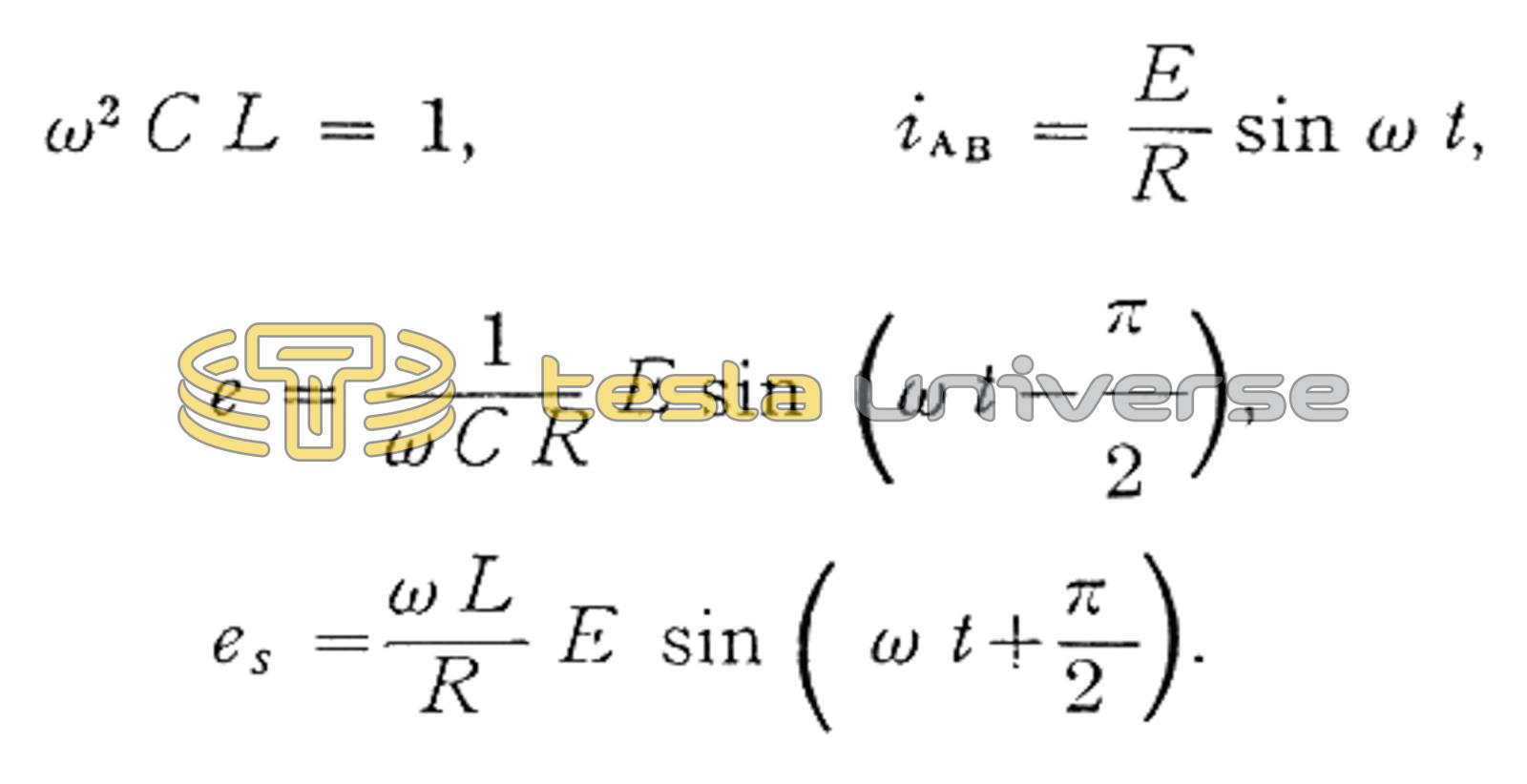
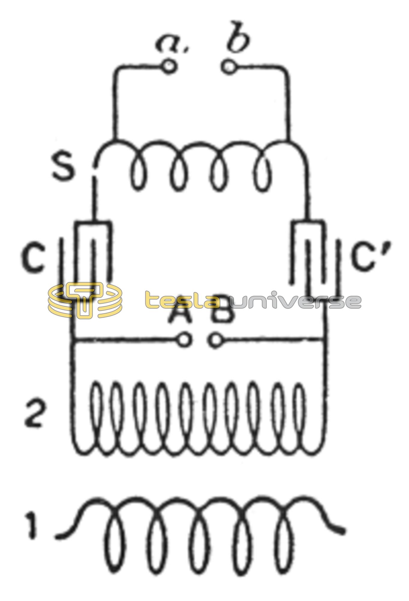
It is easy to see that the smaller R, the greater the ratio of e and es to E. In the high-frequency transformers, the e.m.f. which is multiplied by the coefficient of transformation is that which is produced in circuit 3, it is es, and not the difference of potential, E, applied to the terminals of the condensers, C, C'; the magnitude of E simply determines the length of the spark at A B, and there may exist between the terminals of circuit 3 a difference of potential very much greater. For instance, an induction coil could be placed in shunt with circuit 3 and obtain between a and b (Fig. 96) sparks several centimeters long. d'Arsonval uses this arrangement: he suppresses the secondary of the Tesla coil, and utilizes only the difference of potential which exists between the terminals of a coil of large wire, which is made up of a few turns and forms the circuit, S. The results obtained under these conditions are absolutely the same as those which are obtained with the Tesla coil; they differ only in value of the e.m.f., which is naturally very little.
Where the arrangement of Tesla or d'Arsonval is employed, one essential condition must be fulfilled; namely, the sparks at A B must be white and crackling; above all things, the formation of an arc must be prevented. This condition requires special provisions, because with a short gap generally employed between A and B, the air becomes heated very rapidly, and the high tension of circuit 2 tends to establish an arc.
One of the means employed at the beginning by Tesla, consisted in extinguishing the spark by the aid of a strong current of air directed between the balls, A, B. The second means consisted in utilizing the action of a magnetic field on the current - that is, the magnetic blowout. The balls, A, B, are placed between the poles of a strong electromagnet, the lines of force being perpendicular to the direction of the sparks; the poles of the magnet must be protected from the discharges by means of heavy plates of mica. The magnetic blowout is more affective than the air; the latter has been much simplified by d'Arsonval, who instead of blowing the air between stationary balls, moves the spark through the air. In the d'Arsonval system, the balls, A, B, or the rods which replace them, are mounted on a small electric motor which causes them to describe a circle from 10 cm. to 20 cm. in diameter; the sparks form in this manner at different points, and the duration of a revolution is sufficient to allow the air heated by a spark, to regain the temperature of the surrounding air, before a new spark is formed at the same point.