TCBA Volume 15 - Issue 1
Page 18 of 18
In Closing
Before you go pushing the kitchen sink on top of your little table top coil, it is only fair to say that the balancing and proportioning of these “special systems” is an acquired art perfected only by a “laying upon of the hands”. The commensurate spark quenching, power balancing, coupling, etc. are assumed to be perfect for large loadings. To achieve 6-7 times the output resonator length, a Tesla magnifier system is a must! The resonator system should be directly, and not magnetically coupled to a tuned source of high voltage resonant power of low impedance. Duane Bylund has done this with his solid state system, and we have done it with our disruptively discharged magnifiers.
A couple of quick secrets. Make your resonator contain a minimum of 25 millihenries of inductance if you work above 5 kva. Use a minimum of three times you resonator's winding length as a guide for the diameter of a toroid. Small diameter resonators, under 3 inches, are best made up to at least 6 to 1 length to diameter ratios. These give immediate, quick results with large terminal loadings and lower powers. Short, fat resonators of 2 or 3 to 1 ratio are the most efficient performers, but are difficult to fine tune, requiring the hand of experience to bring to best results. These latter resonators demand higher power operation as well. We find that, at high powers, a stepped terminal capacitance works well. Start with smaller toroids and stack or transition to much larger units. Direct all your efforts into quenching your arcs well! A simple rotary, by itself, is no good at all for high power, tightly coupled magnifier operation! Utilize lots of series gaps in your system to spread the dissapation of the spark energy out over a number of gaps. Heroic efforts are demanded in this area.
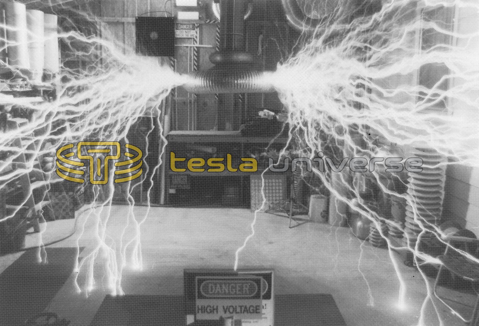
I now offer a photo of a recent effort with magnifer #11-D which has a novel manner of mounting and operation. The system consumes no floor space! This system is seen operating at a power level of 4.5 kva with a 10" X 24" resonator. The total tank capacitance is .025 ufd. The wall mounted driver coil uses a 10 turn primary of 62 uh and a driver coil of 14" X 20" wound with #10 wire. We are coupled up in the driver to, K=.45. The hollow resonator is tight wound with #16 magnet wire and left uncoated. The transmission line to the inverted resonator is a 1.25" copper pipe contacting a 12" X 3" base toroid. The terminal loading is a 20" X 5" toroid with a 36" aluminum spreader cone transitioning to a 45" X 10" toroid. The final tune is about 125 khz. We use an 8 point series-quench rotary gap at about 700-800 interupts per second which uses (16) .180 inch diameter tungsten electrodes. These work well up to 9kva loadings. The longest sparks are 130" point-to-point (straight line) seen exiting the picture.