TCBA Volume 2 - Issue 1
Page 12 of 18
The Precise Measurement of Output Potentials in a Tesla Type Air Core Resonant Transformer System
by D.C. Cox, B.S., Phy.
Introduction
Many Tesla coil enthusiasts have constructed air core resonance transformer systems capable of producing electric discharges with lengths varying from a few inches to several feet through ambient air. Old timers have employed conventional D.C. system measurements as “4 inches representing 100 Kv” and “6 feet being representative of 1 megavolt.”
Our research work involves producing high frequency air core resonant transformer systems for commercial and industrial testing procedures such as particle accelerators and X-ray production at relativistic energy levels. Such work demands accurate measurements of the output potentials of these systems. We have developed accurate methods of measuring and calculating the potentials developed by these systems.
Calculating Techniques
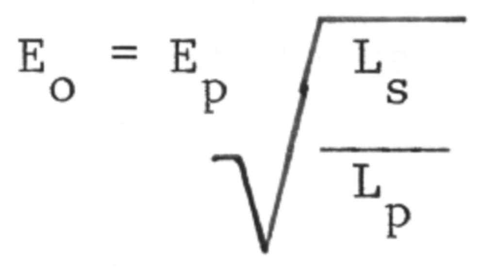
The theoretical maximum potential rise in a resonant transformer system is governed by the equation:
where: Eo = peak output potential
Ep = primary circuit resonant potential
Ls = inductance of secondary coil in microhenries
Lp = inductance of primary coil in microhenries
The maximum peak output potential usually occurs in the first 2-3 cycles of oscillation. The primary resonant 2 potential (E) is defined by:
In actual practice the Ep is twice the rms applied potential. This may be reduced to
As an example, a 12 kv (rms) neon sign transformer has a resonant system potential of 24 kv. This potential appears across the capacitor and inductor. If rf chokes are used in series with the two supply leads from the transformer this resonant potential does not appear across the transformer winding. If these chokes are omitted, this higher resonant potential will appear across the transformer winding and will eventually break it down.
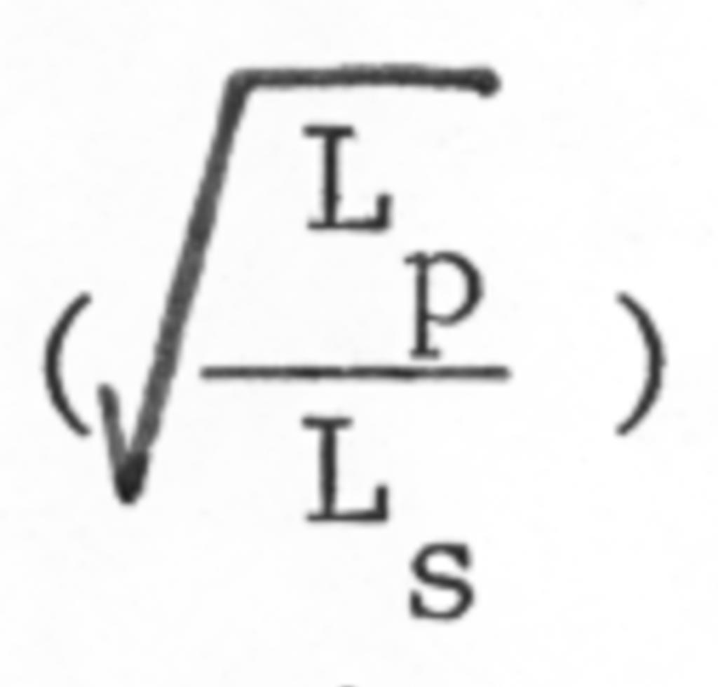
The inductance ratio of the two coils
must be determined which necessitates an accurate calculation of the individual self inductance of each coil. The inductance of an inductor depends entirely on its geometry, and in the case of a Tesla type inductor, the inductance varies considerably depending on the type of inductor under consideration.


