TCBA Volume 2 - Issue 1
Page 3 of 18
Input - Output
Q. Why is cotton covered wire so superior?
A. Tesla coil builders like it because it soaks up shellac quite nicely. After several coats and light sanding, it provides a neatly anchored and nice looking secondary. Also, it gives a bit better separation of turns than plain enamel covered wire.
Q. Why do some coil makers use a flat primary?
A. The choice of primary is a matter of personal preference. Chances are, its popularity is due to ease of construction. Another advantage is that it provides loose coupling and good separation from the secondary. However, any primary properly coupled and of sufficient size will be just as effective.
Q. I once saw a Tesla coil in a 1964 Popular Electronics magazine. Do you have any information on it?
A. The article appeared in the July issue. It was a neat looking unit but in need of some design changes. For one, a 2000 closely wound secondary is prone to flash-over between the turns. Secondly, there is little advantage in a 30-turn primary. Perhaps the worst feature was the use of a needle gap. This is a no-no.
Q. Why is the capacitor so often placed across the power transformer secondary?
A. I found no difference in placement of the capacitor whether it was across the circuit or in series with it. However, there may be an advantage in placing multiple units at various positions. Tesla often applied this principle (see Colorado Notes, page 403 as one example).
Q. Is it possible to build a smaller scaled model of the Reukema coil featured in Volume 1 #1 of TCBA NEWS?
A. Yes, you can change ratios of any construction project. I built one about 1/3rd the size of the original and was able to get a 4-5' spark on 3/4 Kw.
Q. I am experimenting with a conical coil excited by a 11,000 volt, .340 amp transformer. Unfortunately, I am getting a power arc across the rotary gap. Any suggestions?
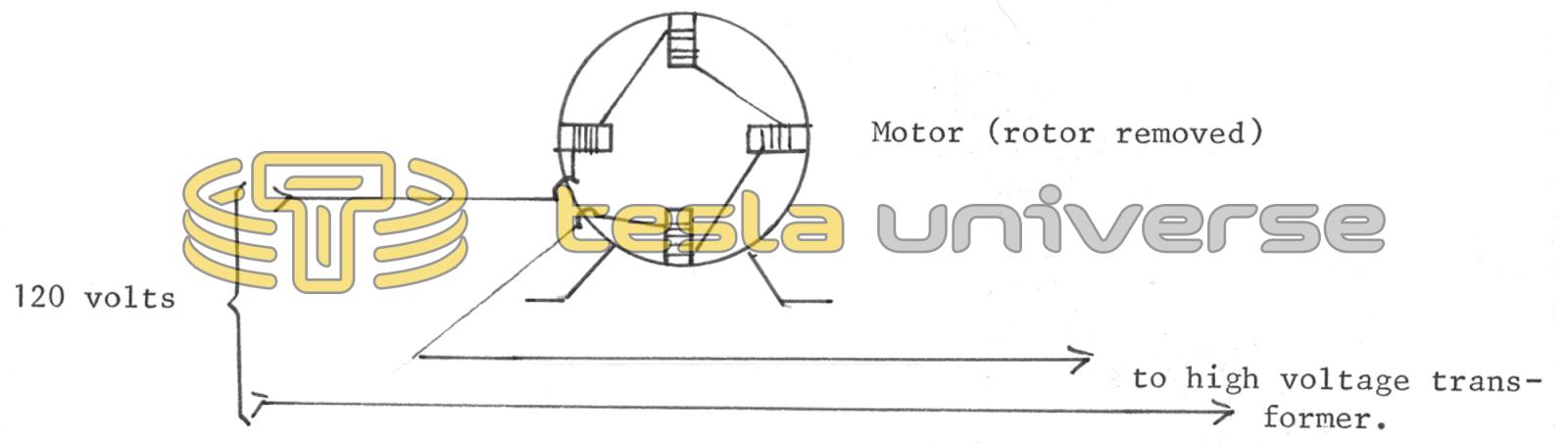
A. Assuming that you are using rf chokes in series with the high voltage output (see diagram of circuit, Volume 1 #2, page 6), it may be necessary for you to install a reactance coil in series with the primary on the low voltage side. Wind 50-100 turns of heavy wire around an iron core or bundle of iron wire. Another alternative is to use the field coils of a motor (the larger the better). Remove the rotor and connect as shown in the diagram below. This idea works fine on low power units. The wire in a motor might be too small for a unit such as yours. In that case, remove the four field coils and wind 4 coils of 25-50 turns of heavy wire, say #10. You can employ taps so that there is a choice of 0, 1, 2, 3, or 4 coils in use.
Another factor that may be involved is the size of the capacitor you are using. Arcing tends to occur when the capacitor has too small a value. You can use fewer primary turns and a larger capacitance.