
TCBA Volume 2 - Issue 1
Page 8 of 18
TCBA Member Activity
Thorn Mayes W6AX
(part 2)
Design
The Quaker Oats Company deserves a lot of credit for electronics development in the U. S. as they have since 1915 to my knowledge, packaged their product in excellent cardboard cylinders that have been used by experimenters for years.
Their small oatmeal boxes are 4 inches diameter by 7-1/8 inches long, are strong and are available. One inch thick tight fitting wooden discs mounted in the ends permit making coil forms 7-1/8 - 14-1/4 - and 21-3/8 inches long so they were selected for the secondaries.
Primary
The primary was made of copper (or brass) ribbon 1/2 inch wide .015 inches thick, wound in a spiral of eight turns with an inside diameter of 5 inches outside of 8 inches. This ribbon is held in saw cuts in eight radial supporting arms that are glued, not nailed, to a center support.
After the primary was completed, it was mounted at right angles to a piece of plywood that had been marked off into two inch squares. The four inner turns were excited as shown by the wiring diagram on curve T-2 and readings of field strength were taken with an absorption frequency meter. These readings were plotted on curve T-2 and show the field pattern generated by the primary. Three secondary coil heights are also shown in dotted lines on this curve.
Secondary
To evaluate the effect of design changes, a grounded disc of 1/4 inch mesh hardware cloth was mounted above the coil under test so that it could be changed in height to measure spark length. The test arrangement is shown in Figure 2.
Ten secondaries were wound on 7-1/8 inch high forms and tested to determine the effect of winding and insulation changes. Turns varied from 185 to 350, wire size from #20 to #32, coverings-bare, enamel, enamel single cotton and double cotton insulation. Some coils were close wound, some with spaced turns. Several were wound, tested, then given a coat of air-dry varnish and retested.
There was little difference in the spark lengths generated by the different secondaries although the spark from the 350 turn coil was slightly longer than from the 185 turn coil. Enameled wire was equivalent to bare, and size made no noticeable difference. I would therefore recommend #24 to #28 wire size with whatever insulation is available, though a final covering of cotton soaks up varnish and gives a good mechanical structure. On large coils spacing the turns will use less wire.
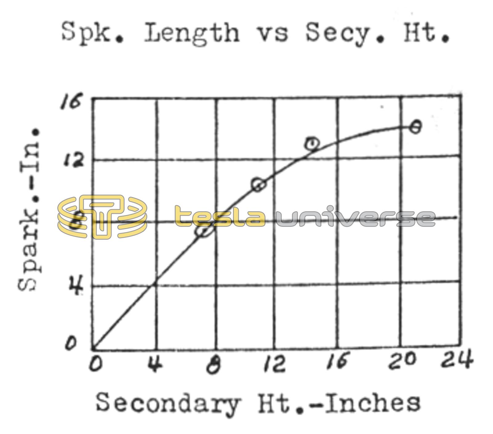
Coil #G was typical of the 7-1/8 inch height design. #J with 10-3/4 inch height and #e 14-1/4 inches were then wound and for a check on greater height, #G was stacked on top of #E.
Dimensions and performance of these four coils is shown in Figure 3. Spark length is plotted against coil height in Figure 4 which shows that little is gained by exceeding 14-1/4 inch height.
All secondaries had a wooden disc in the top end of the secondary winding. These brass discharge balls are 2 inches in diameter and were from corner posts of early brass beds.
Fig. 3
Secondary Design and Tests.
| Coil # | Spark (in.) | Height (in.) | Sec. Turns | Freq. kHz | Prim. Turns |
|---|---|---|---|---|---|
| G | 7 1/2 | 7 1/8 | 225 | 1050 | 1 3/4 |
| J | 10 | 10 3/4 | 287 | 800 | 2 1/2 |
| E | 12 1/2 | 14 1/4 | 380 | 570 | 4 3/4 |
| E+G | 14 1/2 | 21 3/8 | 305 | 460 | 6 1/4 |
Transformer
Small neon sign or oil-burner ignition transformers should be available in used condition for around $15. They are rated 10.000 to 12,000 volts with grounded center taps on the secondaries so 5,000 to 6,000 volts can be obtained from them at 20 to 30 milliamperes current. All pictures of spark displays were taken using one of these transformers.
The filter across the primary shown in Figure 1 made of two small. 01 micro farad capacitors will reduce the possibility of interference back thru the power line.
Spark Gap
The spark gap is an important part of the system. A quenched gap would give a slightly longer spark from the Tesla coil but it would require more attention than the gap shown. Dimensions are not critical and can be scaled from the picture. Cooling fins are important and were provided by turning the two gap sections from one inch diameter aluminum rod, with sparking surfaces reduced to 1/4 inch diameter.
Condenser
Most Tesla coil failures can be traced to use of a condenser with too little capacity. The best design is the mica construction built in cast aluminum cases by Dubilier and Wireless Specialty Apparatus Company around 1920 for the Navy for use in spark transmitters. They came in units rated 12,500 volts .004 Mf. capacity. Three of these would be adequate for this small Tesla coil.