Nikola Tesla Articles
A New Form of Induction Coil
READ AT THE FOURTEENTH GENERAL MEETING OF THE AMERICAN INSTITUTE OF ELECTRICAL ENGINEERS, ELIOT, ME., JULY 26-28, 1897, BY PROF. ELIHU THOMSON.
The induction coil presently to be described, it is believed, constitutes a new type employing the principle of a "substitute primary" or "secondary primary," which principle has been applied by me in a variety of ways.
The prime object of this coil is to permit the direct connection to circuits of considerable potential for obtaining energy for the production of high-potential discharges, like those of a Ruhmkorff coil for working Roentgen-ray vacuum tubes, and for such like purposes. The object, also, was to avoid the employment of banks of lamps or storage batteries, and to limit the energy consumed to only that amount required to work the coil itself. Furthermore, no larger condensers than those ordinarily used with an induction coil of equal capacity are needed, and no air-blast, while the coil as a whole is still available as an ordinary Ruhmkorff without change in its structure or connections.
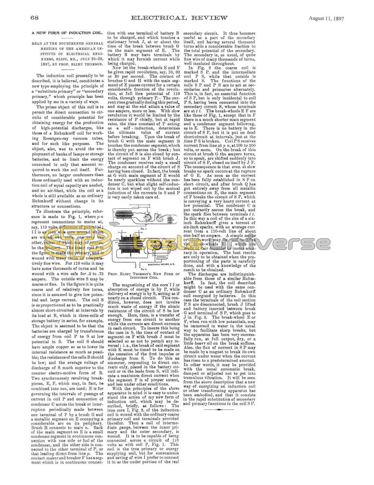
To illustrate the principle, reference is made to Fig. 1, where p n represent connections to mains at, say, 110 volts difference of potential; I I is an iron wire core around which are wound two coils, one over the other, either of which may, of course, be the primary. The inner coil P in the figure is made the primary, and is wound with many turns of comparatively fine wire. For 110 volts it may have some thousands of turns and be wound with a wire safe for .5 to .75 ampere. The outside wire S may be coarse or fine. In the figure it is quite coarse and of relatively few turns, since it is assumed to give low potential and large current. The coil S is so proportioned as to be practically almost short-circuited at intervals by its load at B, which is three-cells of storage battery in series, for example. The object is assumed to be that the batteries are charged by transference of energy from coil P to S at low potential in S. The coil S should have ample copper so as to lower its internal resistance as much as possible; the resistance of the cells B should be low; and the average voltage of discharge of S much superior to the counter electro-motive force of B. Two synchronously revolving break-pieces, E, F, which may, in fact, be combined into one, are used; E is for governing the intervals of passage of current in coil P and connection of condenser C across the break or interruption periodically made between one terminal of P by a brush G and a metallic segment on E occupying a considerable arc on its periphery. Brush H connects to main n. Back of the main segment on E is a small condenser segment in continuous connection with one side or foil of the condenser, and the other side is connected to the other terminal of P, or that leading direct from line p. The contact maker and breaker F has a segment which is in continuous connection with one terminal of battery B to be charged, and which touches a stationary brush J, at or about the time of the break between brush G on the main segment of E. The battery B may have terminals by which it may furnish current while being charged.
Now let the break-wheels E and F be given rapid revolution, say, 10, 20 or 30 per second. The contact of brushes G and H with the main segment of E passes current for a certain considerable fraction of the revolution, at full line potential of 110 volts, through primary P. The current rises gradually during this period, and may at the end attain a value of one ampere, more or less. With slow revolution it would be limited by the resistance of P chiefly, but at rapid rates, the time constant of P acting as a self-induction, determines the ultimate value of current before breaking. Upon the break of brush G with the main segment it touches the condenser segment, which is thereby put across the break; but the circuit of S is also closed by contact of segment on F with brush J. The condenser receives only a small charge on account of the circuit of S having been closed. In fact, the break at G with main segment of E would be nearly sparkless without the condenser C, but what slight self-induction is not wiped out by the mutual induction of the currents in S and P is very easily taken care of.
The magnetizing of the core I I or absorption of energy is by P, while delivery of energy is by S, acting as if nearly on a closed circuit. This condition, however, does not involve much waste of energy if the ohmic resistance of the circuit of S be low enough. Here, then, is a transfer of energy from one circuit to another while the currents are direct currents in each circuit. To insure this being the case in S, the time of contact of segment on F with brush J must be selected so as not to permit any reversal; i. e., the break of said segment with K must be timed to be made on the cessation of the first impulse or discharge from S. To do this an ammeter, responding to direct currents only, placed in the battery circuit or in the leads from S, will indicate a maximum direct current when the segment F is of proper extent, and less under other conditions.
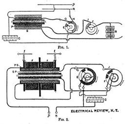
With the principles of the above apparatus in mind it is easy to understand the action of my new form of induction coil, which may be described, briefly, as follows: The iron core I, Fig. 2, of the induction coil is wound with the ordinary coarse primary coil and terminals provided therefor. Then a coil of intermediate gauge, between the inner primary and the outer secondary, is wound. It is to be capable of being connected across a circuit of 110 volts as with coil P, Fig. 1. This coil is the true primary or energy supplying coil, but for convenience and saving of wire I prefer to connect it in as the under portion of the real secondary circuit. It thus becomes useful as a part of the secondary itself, and having several thousand turns adds a considerable fraction to the total potential of the secondary. The secondary is, as usual, of quite fine wire of many thousands of turns, well insulated throughout.
In Fig. 2 the coarse coil is marked S P, and the intermediate coil P S, while that outside is marked S. The functions of the coils S P and P S are to act as secondaries and primaries alternately. This is, in fact, an essential function of S P, but is only incidental to coil P S, having been connected into the secondary circuit S, whose terminals are at t t. The break-wheels E F are like those of Fig. 1, except that in F there is a much shorter main segment and a condenser segment following, as in E. There is no battery in the circuit of S P, but it is put on dead short-circuit at intervals, just at the time P S is broken. Coil P S receives current from line at p n, at 100 to 200 volts, or more. On the break of this circuit at brush G the ampere turns, so to speak, are shifted suddenly into circuit of S P, closed on itself by J F. The consequence is that even at slow breaks no spark occurs at the rupture of G E. As soon as the current has been fully established in S P on short circuit, and after brush Q has got entirely away from all metallic connections on E, the main segment of F breaks the circuit of S P, which is conveying a very heavy current at low potential. The condenser C is put instantly across the break, and the spark flies between terminals t t. In this way a coil of the size of a six-inch Ruhmkorff gives a torrent of six-inch sparks, with an average current from a 110-volt line of about one-half an ampere. A simple motor or clock-work may be used to drive the break-wheels E , which are made of fair diameter to insure accuracy in operation. The best results are only to be obtained when the proportioning of the parts is carefully done, and with a knowledge of the result to be obtained. The discharges are indistinguishable from those of a similar Ruhmkorff. In fact, the coil described might be used with the same condenser C as an ordinary Ruhmkorff coil energized by batteries. In this case the terminals of the coil section P.S are disconnected, brush J lifted and battery inserted between brush G and terminal of S P, which goes to J in Fig. 2. The break-wheel E or F, when run with low potentials, may be immersed in water in the usual way to facilitate sharp breaks, but the apparatus has been very successfully run, at full output, dry, or a little heavy oil on the break suffices. Also, the flux of current in S P may be made by a magnet to break its own circuit under water when the current has risen to a predetermined amount. In other words, it may be provided with the usual automatic break, damped or adjusted not to get into tremulous vibration. It will be seen from the above description that a new way of energizing an induction coil or other transforming apparatus has been embodied, and that it consists in the rapid substitution of secondary and primary functions in the coil S P.