Nikola Tesla Articles
Syntonic Wireless Telegraphy - Part 1
The very rapid advances which have been made in the art of telegraphy through space continue to attract much attention to this fascinating subject. What was stated yesterday to be impossible has now become possible, and what we regard as almost insurmountable difficulties may be removed in the immediate future. The number of experimenters working in this field has increased, as many workers, who, some time ago, had little or no faith in the practical utility of wireless telegraphy, have now changed their minds and are taking up the subject. I believe it to be necessary, before I proceed to deal with the subject, to state that in my opinion a large amount of inaccurate and misleading information is being from time to time published upon it in the daily and even in the scientific press. I shall endeavour to correct some of the misstatements which have been made.
As the title of my Paper implies, it is my intention first to describe fully the efforts I have made in order to tune or syntonise the wireless system, efforts which I am glad to say have been crowned with complete success. I also wish to mention something of the difficulties encountered in promptly publishing the results (whether successful or otherwise) obtained in the course of my experiments. A commercial concern, such as the one with which I am working, does not exist solely for the advancement of science, but especially for the purpose of securing a pecuniary return to those who have braved risks and undertaken sacrifices in assisting and forwarding the necessary experimental work. It is often considered possible that certain new methods and results may, if prematurely published before being fully patented, be utilised by persons whom I might call business rivals, thus preventing those who have borne the initial cost of the first tests from benefiting in a fair measure. I am, therefore, frequently prevented from promptly publishing the methods by which I have obtained interesting results. By quoting the dates of the British patent specifications and other publications, I hope to be able to establish, to a certain extent, the dates at which the various systems or methods were worked out. It may probably surprise some of you when I mention how comparatively long ago some of the patents which I shall discuss tonight were applied for and perfected. Last winter I had the honour of describing before the Royal Institution of Great Britain most of the success obtained up to that date in communicating by means of my system from one place to another. It is my desire in this Paper to give a description of the further progress made, with special reference to the results obtained by tuning or syntonising the installations. So long as it was possible to work only two installations within what I may call their sphere of influence, a very important limit to the practical utilisation of the system was imposed. With simple vertical wires, as shown in Fig. 1A and Fig. 2, connected directly to the coherer and spark gap at the receiver and transmitter, as used by myself before 1898, no really satisfactory tuning was possible. It was, however, possible to obtain a certain selection of signals if various stations in the vicinity used vertical wires differing very considerably in length. Thus two stations communicating over a distance of, say, 5 miles and using wires 100ft. long, would not interfere with the signals transmitted by the other two stations, say 2 miles from the first, which were using aerials only 20ft. long, and communicating over a distance of about 1 mile. The new methods of connection which I adopted in 1898, i.e. (see Fig. 8), connecting the receiving aerial directly to earth instead of to the coherer, and by the introduction of a proper form of oscillation transformer in conjunction with a condenser so as to form a resonator tuned to respond best to waves given out by a given length of aerial wire, were important steps in the right direction. I referred extensively to this improvement in the discourse delivered before the Royal Institution on Feb. 2, 1900, and my first British patent specification referring thereto was applied for on June 1, 1898, No. 12,326, and published in due course. This mode of connection was also discussed by the technical press.**
It is remarkable that eminent scientists and engineers, such as Prof Slaby and G. Kapp, who have been good enough to discuss my work on wireless telegraphy, should be so badly informed on the subject in general as not to know that this method and many other improvements on my original system have been in use by myself and my assistants for several years. I wish to give you an illustration of what I mean. In a Paper on "Tuned or Multiple Wireless Telegraphy," by Prof. Slaby, of Charlottenburg, read on Dec. 22, 1900, and published in a special number of the Elektrotechnische Zeitschrift, he stated: "Up to the present the following method has been followed without exception: — The receiving wire was suspended insulated and attached at the lower end to the coherer, the other pole of which was connected to earth."
Again, G. Kapp, in an editorial review in the same publication, states: "According to the Slaby d'Arco system and in opposition to the Marconi system the receiving wire is earthed." The inaccuracy of these statements is very apparent if we compare them with the description given by myself nearly three years previously in the British patent applied for, as I have remarked, on June 1, 1898, published in July, 1899, and openly discussed by the scientific press of this and other countries a long time previous to the date of Slaby's Paper. At line 7, page 1, of my description, will be found the following passage: "According to this invention the conductor (aerial) is no longer insulated, but is connected to earth through the primary of an induction coil, whilst the ends of the imperfect contact (or coherer) are connected to the ends of the secondary one of the connections passing through a condenser." As you will notice, nothing is said in this patent of the necessity of insulating the vertical wire of the receiver. If the system described here had not been used by me I very much doubt whether we should have succeeded in maintaining communication with the East Goodwin lightship during 1899, in maintaining communication across the English Channel that same year during the meeting of the British Association at Dover, and in supplying the Admiralty in the course of the year 1900 with 32 installations, all of which passed an official 100 kilometre test (most of the distance being over land) at the rate of about three installations per week.
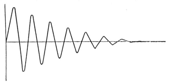
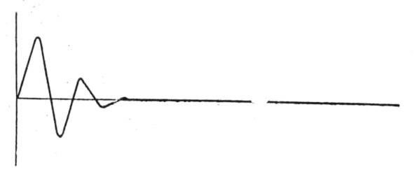
Leaving this subject for the present, I shall endeavour to describe the various steps made in the development of my syntonic system. I realised a long time ago that one great difficulty in achieving the desired effect was caused by the action of the transmitting wire. A simple straight rod in which electrical oscillations are set up forms, as is well known, a very good radiator of electrical waves. If this was in the beginning an advantage, by allowing signals to be received with a small amount of energy over considerable distances, it proved later to be one of the chief obstacles in the way of obtaining good resonance in the receiver. Now, as Dr. Fleming points out so clearly in his Cantor lectures on "Electrical Oscillations and Electric Waves," delivered before this Society in November and December of last year, there is in connection with this part of the subject one point of great interest. "Both theoretical and experimental research show that in the case of conductors of a certain form the electric oscillations die away with great rapidity." In all what we call good radiators, electrical oscillations set up by the ordinary spark discharge method cease, or are damped out very rapidly, not necessarily by resistance, but by electrical radiation removing the energy in the form of electric waves. Many mechanical analogies can be quoted which will point out the necessity of designing a persistent oscillator, in order that syntony may become apparent in properly tuned resonators. Acoustics furnish us with numerous examples of this fact, such as the resonance effects produced by the well-known tuning-fork experiment. Other illustrations of this principle may be given, e.g., if we have to set in motion a heavy pendulum by means of small thrusts or impulses, these must be timed to the period of oscillation of the pendulum, since otherwise its oscillations will not acquire any perceptible amplitude. An illustration of this fact occurred to me some time ago while I was watching the ringing of great bells in an Italian cathedral. As most of you probably know, the bells in many churches in Italy, as elsewhere, are rung from the bottom of the tower by means of ropes attached to the bells. The largest bells weigh several tons, and it usually requires two men to work for perhaps two minutes on the ropes before the combined effect of their pulls is sufficient to get the bell to attain an amplitude large enough to cause the hammers to strike. I observed on the occasion to which I allude that it required for each bell a number of well-timed pulls on the ropes in order to get them to swing, the larger bells requiring impulses further apart, i.e., of a lower frequency, than the smaller ones. It is perfectly obvious that if the pulls on the ropes had been wrongly timed it would have been impossible with the same amount of power to ring the bells. The same kind of effect happens in a very small fraction of a second (instead of several minutes) when we try to induce electrical oscillations in a good resonator. If the form of this resonator be such as to cause it to be a persistent vibrator, i.e., one in which the electrical oscillations are not rapidly damped by resistance or radiation of waves, then it is necessary for us to employ a number of properly timed electrical oscillations radiated from a persistent oscillator tuned to the period of the resonator we desire to affect.
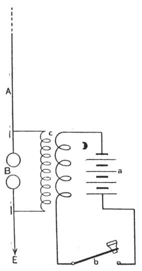
As I pointed out before, a transmitter consisting of a vertical conductor as shown in Fig. 1 is not a very persistent oscillator. Its electrical capacity is comparatively so small and its capability of radiating waves so great, that the oscillations which take place in it must be considerably damped. In this case receivers or resonators of a considerably different period or pitch will respond and be affected by it. From the results obtained it would seem as if the transmitter were sending out a great variety of electric waves, resembling therefore a source of white light, and that each resonator picks out and responds to its own particular wave length. This view, however, is incorrect; the fact that, given certain conditions, various resonators will respond, even if their period be different from the natural period of oscillation of a transmitter, is to be accounted for by the consideration that all the energy of the transmitter is radiated in only one or two swings, with the result that oscillations may be induced in resonators of different periods, whilst, if the same amount of energy be distributed in a great number of individual feeble impulses, their combined effect can only be utilised or detected by a resonator tuned so as to respond to their particular frequency. The tuned resonator will not then respond to the first two or three oscillations but only to a longer succession of properly timed impulses, so that only after an accumulation of several swings does the E.M.F. becomes sufficient to break down the insulation of the coherer, and cause a signal to be recorded.
Notwithstanding the disadvantages for obtaining electrical tuning, attributed to the form of transmitter shown in Fig. 1, selection of messages is possible when using, say, two or three transmitters having wires of considerably different lengths, and the induction coil or oscillation transformers on the receivers wound with varying lengths of wire in their secondary circuits, in order to cause them to be in tune or resonance with the length of wave of the transmitted oscillations, as pointed out in my British patent, No. 12,326, dated June 1, 1898. At page 1, line 19, this reads: "It is desirable that the induction coil should be in tune or syntony with the electrical oscillations transmitted, the most appropriate number of turns and most appropriate thickness of wire varying with the length of wave transmitted." The following experiment, which has been successfully tried, proves this point. At St. Catherine's, Isle of Wight, we had a transmitting station having a vertical wire 45 metres long, and at sea, 10 miles from our receiving station at Poole, a ship with transmitting wire of 27 metres. It is, therefore, obvious that the wave length of the electric oscillations radiated from St. Catherine's differed considerably from that radiated from the ship. Now, if at the receiving station at Poole we connected to a vertical wire two receivers, one having an induction coil with secondary in tune with the length of wave emitted by St. Catherine's and the other with that emitted by the 27-metre wire on the ship, if St. Catherine's and the ship transmit simultaneously two different messages, these will be picked up at Poole, and each message will be reproduced distinctly on its receiver. I pointed out in a patent specification dated Dec. 19, 1899, No. 25,185, page 2, that the best results are obtained when the length of wire of the secondary of the induction coils is equal to the length of the vertical wire used at the transmitting station, therefore the length of the secondary of the receiving induction coils was made equal to that of the transmitting wire. (Something of the same kind has been lately noticed by Prof. Slaby in what he calls an extension wire.)
These results, although in a way satisfactory, did not appear to my mind a complete solution of the problem. I found it impossible to obtain the two messages at the receiving station if the two transmitting stations were placed at equal distances from it. The following considerations may perhaps explain this failure. If the 27-metre transmitting wire was placed at the same distance from Poole as the 45-metre one, i.e., 31 miles, the waves emitted by the 27-metre wire would be too weak when they reached Poole to affect the receiver. On the other hand, if the 45-metre transmitter was placed at 10 miles from the receiver, then the waves radiated by it would be so strong as to affect the receiver, tuned to respond to the 27-metre transmitter, and blur its signals.
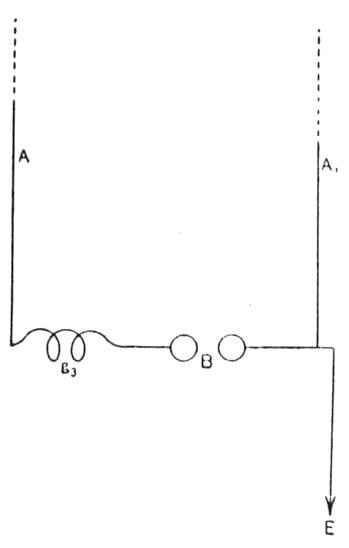
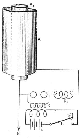
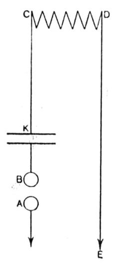
It thus became apparent that some different form of less damped radiator was necessary in order to obtain more practical and more useful results. I carried out a great number of experiments by adding to the radiating and receiving wires inductance coils, on a principle similar to that suggested by Lodge in his 1898 patent (No. 29,069), but without obtaining any satisfactory results. The failure was probably due to the fact that the electrical capacity of the exposed conductors became too small in proportion to their inductance. I then tried various methods for increasing the capacity of the radiating system. The first and obvious mode of effecting this is by an augmentation in the size of the exposed conductor, but this method is not entirely satisfactory, in consequence of the circumstance that an increased surface means increased facility for radiating the energy during the first oscillations, and also because large plates or large exposed areas are impracticable on board ship, and are always difficult to suspend and maintain in good position during windy weather. The way out of the difficulty was discovered by adopting the arrangement shown in Fig. 3. Here we have an ordinary vertical radiator placed near an earthed conductor, the effect of the adjacent conductor being obviously to increase the capacity of the electrical radiating wire without in any way increasing its radiative power, and, as I had expected, syntonic results were not difficult to obtain with such an arrangement. Mention of this method has been made by Capt. Ferrie, one of the members of the French Commission which was present at the tests carried out across the English Channel in 1899, in a Paper on wireless telegraphy. See Paper "Etat Actuel et Progrès de la Télégraphie Sans Fil," read before the Congrès International d'Electricité, Paris, 1900.*** Satisfactory results were obtained, and I was encouraged to continue my researches in order to improve the system. Early in 1900 I obtained very good results with the arrangement shown in Fig. 4. This arrangement is fully described in a British patent application applied for by myself on March 21, 1900, No. 5,387. In it the radiating and resonating conductors take the form of a cylinder, the earthed conductor being placed inside. This form of radiating and receiving areas is much more efficient than the one I have previously described. One necessary condition of this system is that the inductance of the two conductors should be unequal, it being preferable that the large inductance should be joined to the non-earthed conductor. I presume that, in order to radiate the necessary amount of energy, it is essential that there should be a difference in phase of the oscillations in the two conductors, as otherwise their mutual effect would be to neutralise that of each other. In the first experiments mentioned by Capt. Ferrie this was obtained by simply using an earthed conductor shorter than the radiating or resonating one. When I used an inductance between the spark-gap or oscillation producer and the radiating conductor, I found it possible to cause the electrical period of oscillation of the receiving cylinder to correspond to that of one out of several transmitting stations, from which one alone it would receive signals. The results obtained by this system have been remarkable. By using cylinders of zinc only 7 metres high and 1.5 metres in diameter, good signals could easily be obtained between St. Catherine's, Isle of Wight, and Poole (distance 31 miles), these signals not being interfered with or read by other wireless telegraph installations worked by my assistants or by the Admiralty in the immediate vicinity. The closely adjacent plates and large capacity of the receiver cause it to be a resonator possess- ing a very decided period of its own, i.e., it becomes no longer apt to respond to frequencies which differ from its own particular period of electrical oscillation, nor to be interfered with by stray ether waves, which are sometimes probably caused by atmospheric disturbances, and which occasionally prove troublesome during the summer. It seemed very remarkable to me during my first test that an arrangement similar to that shown in Fig. 4 should prove to be a good radiator and should enable such a considerable distance to be achieved with cylinders of so moderate a height. It is probable that the great majority of the electrostatic lines of force pass directly from one cylinder to the other, but it must be also true that a certain number leave the outer part of the external cylinder, exactly as in the case of an ordinary radiator. The receiver is not shown in the sketch, but consists of similar cylinders to those used for transmitting the receiving induction coil or oscillation transformer, being placed where the spark-gap is shown in Fig. 4. The capacity of the radiator due to the internal conductor is, however, comparatively so large that the energy set in motion by the spark discharge cannot all radiate in one or two oscillations, but forms a train of slowly damped oscillations, which is just what is required. A simple vertical wire, as shown in Fig. 1, may be compared with a hollow sphere of thin metal which, when heated, would cool very rapidly, and the concentric cylinder system with a solid metal sphere, which would take a very much longer time to cool. Mr. W. G. Brown suggested, in a patent specification dated July 13, 1899, No. 14,449, the use of two conductors of equal length joined to each side of the spark-gap, but he did not describe the inductance in series between them and the spark-gap, which, according to my experience, is absolutely essential for long-distance work. Another very successful syntonised transmitter and receiver system was the outcome of a series of experiments carried out with the discharge of Leyden jar circuits. Taking for granted that the chief difficulty with the old system, as shown in Fig. 1, lies in the fact, as already stated, that the oscillations are very dead beat, I tried by means of associating with the radiator wire a condenser circuit, which was known to be a persistent oscillator, to set up a series of persistent oscillations in the transmitting vertical wire.
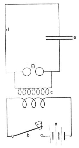
An arrangement as shown in Fig. 6, which consists in a circuit containing a condenser and a spark-gap, constitutes a very persistent oscillator. Prof. Lodge has shown us how, by placing it near another similar circuit, it is possible to demonstrate interesting effects of resonance by the experiment usually referred to as that of Lodge's syntonic jar. But, as Lodge points out,**** "A closed circuit such as this, is a feeble radiator and a feeble absorber, so that it is not adopted for action at a distance." I very much doubt if it would be possible to affect an ordinary receiver at even a few hundred yards. It is very interesting to notice how easy it is to cause the energy contained in the circuits of this arrangement to radiate into space. It is sufficient to place near one of its sides a straight metal rod or good electrical radiator. The only other condition necessary for long-distance transmission is that the period of oscillation of the wire or rod should be equal to that of the nearly closed circuit.
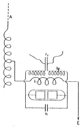
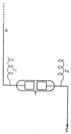
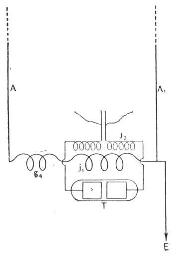
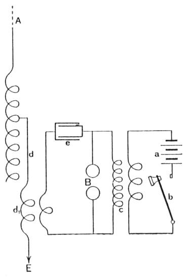
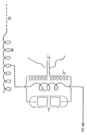
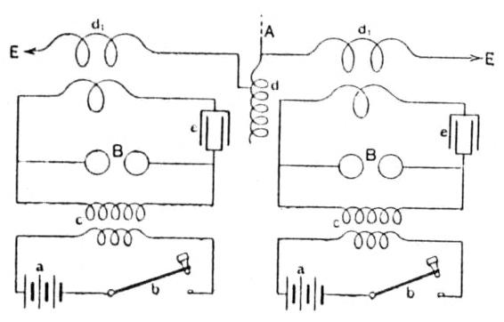
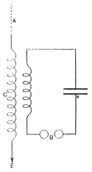
Stronger effects of radiation are obtained if the radiating conductor is partly bent round the circuit, including the condenser (so as to resemble the circuits of a transformer). I first constructed an arrangement as shown in Fig. 14, which consists of a Leyden jar or condenser circuit, in which is included the primary of what may be called a Tesla coil, the secondary of which is connected to the earth or aerial conductor. The idea of using a Tesla coil to produce the oscillations is not new. It was tried by the Post Office officials when experimenting with my system in 1898, and also suggested in a patent specification by Dr. Lodge, dated May 10, 1897, No. 11,575, and by Prof. Braun in the specification of a patent dated Jan. 26, 1899, No. 1,862. My idea was to associate with this compound radiator a receiver tuned to the frequency of the oscillations set up in the vertical wire by the condenser circuit. My first trials were not successful, in consequence of the fact that I had not recog- nised the necessity of attempting to tune to the same period of oscillation (or octaves) the two electrical circuits of the transmitting arrangement (these circuits being the circuit consisting of the condenser and primary of the Tesla coil or transformer, and the aerial conductor and secondary of the transformer). Unless this condition is fulfilled, the different periods of the two conductors create oscillations of a different frequency and phase in each circuit, with the result that the effects obtained are feeble and unsatisfactory on a tuned receiver. The syntonised transmitter is shown in Fig. 7. The period of oscillation of the vertical conductor A can be increased by introducing turns, or decreased by diminishing their number, or by introducing a condenser in the series with it. The condenser C in the primary circuit is constructed in such a manner as to render it possible to vary its electrical capacity. The receiving station arrangements are shown in Figs. 8 and 9. Here we have a vertical conductor connected to earth through the primary of a transformer, the secondary circuit of which is joined to the coherer or detector. In order to make the tuning more marked, I place an adjustable condenser across the coherer in Fig. 9. Now, in order to obtain the best results, it is necessary that the free period of electrical oscillations of the vertical wire primary of transformer and earth connection should be in electrical resonance with the second circuit of the transformer, which includes the condenser. I stated that, in order to make the tuning more marked, I placed a condenser across the coherer. This condenser increases the capacity of the secondary resonating circuit of the transformer, and in the case of a large series of comparatively feeble but properly timed electrical oscillations being received, the effect of the same is summed up until the E.M.F at the terminals of the coherer is sufficient to break down its insulation and cause a signal to be recorded.
In order that the two systems, transmitter and receiver, should be in tune, it is necessary (if we assume the resistance to be very small or negligible) that the product of the capacity and inductance in all four circuits should be equal. A more complete and detailed description of this system is given in a British patent granted to me, dated April 26, 1900, No. 7,777. I have recently found that Prof. Braun has recognised the necessity of tuning the circuits of the transmitter and receiver when using a Tesla coil in order to obtain syntonic effects, but I am not aware that such a proposal was published prior to the description given in the above-mentioned patent.
Although little difficulty has been encountered in measuring the capacity used in the various circuits, the measurement or calculation of the value of the inductance is not so easy. I have found it impracticable by any of the methods with which I am acquainted directly to measure the inductance of, say, two or three small turns of wire. As for calculating the inductance of the secondary of small transformers, the mutual effect of the vicinity of the other circuits and the effects due to mutual induction greatly complicate the problem.
Experiments have confirmed the fact that the receiving induction coils having the secondary wound in one layer and at a certain distance, say 2mm. (to cause the capacity to be so small as to be negligible), have a time period approximately equal to that of a vertical conductor of equal length (see patent granted to G. Marconi, dated Dec. 19, 1899, No. 25,186). If, therefore, we are using an induction coil having a secondary 40 metres long on the receiver, I should use a vertical wire 40 metres long at both transmitting and receiving stations. By so doing I have the two circuits at the receiving station in tune with each other, and I only have to adjust the capacity of the condenser at the transmitter, which can easily be done, either by means of a condenser having movable plates that can be slid, more or less, over each other, or by adding or removing Leyden jars.
If we start with a very small capacity which we gradually increase, a value of the capacity will be reached which will cause signals to be recorded on the receiver. Supposing the receiving system to be within the sphere of action of the transmitter, then the signals will be strongest when the capacity of the condenser is of a certain value. If we still increase the capacity, the signals will gradually die away, whilst if we go on increasing the capacity, and, at the same time, add inductance to the aerial, to keep it in tune with the condenser jar circuit, we are still radiating waves, but these do not affect the receiver. If, however, at the receiving station we add inductance or capacity to the wire A, Fig. 9, and also to the ends of the secondary of J2, we find ourselves able to receive messages from the transmitter although we are utilising waves of a different frequency.
(To be concluded.)
See Electrician from May 31, 1901.
* Paper read before the Society of Arts, May 15.
** See The Electrician, Vol. XLIII., p. 48; also Vol. XLIV., pp. 555-556.
*** See The Electrician, Oct. 26, 1900, p. 22 ("Electrician" Publishing Co.).
**** "The Work of Hertz," by O. J. Lodge, page 7.