Nikola Tesla Books
Books written by or about Nikola Tesla

ditional gaps a and b and it was observed that unless the induction coil be capable of giving a large current, spheres of considerable size were not the best to employ in the usual arrangement of apparatus. The reason was that the arc was formed with difficulty, hence it had to be made shorter, but when the current broke through, the resistance of the small arc was very low and the secondary of the induction coil was short circuited too much. This may not be always true. By using additional gaps the primary was closed during a shorter interval of time and also the secondary was less short-circuited. The latter was an advantage but the former was decidedly a disadvantage because the primary circuit could not vibrate very long. The energy taken from the supply transformer or coil was, of course, smaller. All the results obtained in these experiments seem to indicate, contrary to former opinions, that a higher economy is obtainable with one gap that with a greater number. This observation was, however, made before in the New York apparatus. Finally, two gaps in series were adopted as convenient and giving greater velocity of separation. But the best results were obtained with two electrodes in the form of toothed disks rotated in opposite directions. The apparatus in this form was more troublesome to run but worked decidedly better. In this form also an improvement was practicable, which I have since adopted in some form of mercury breaks, and that was to make the number of teeth on each disk such that the total number of the makes and breaks was the product of both the numbers. In this form a small number of teeth was found sufficient for a great number of breaks and the arc could not follow from one to an adjacent tooth.
Colorado Springs
July 28, 1899
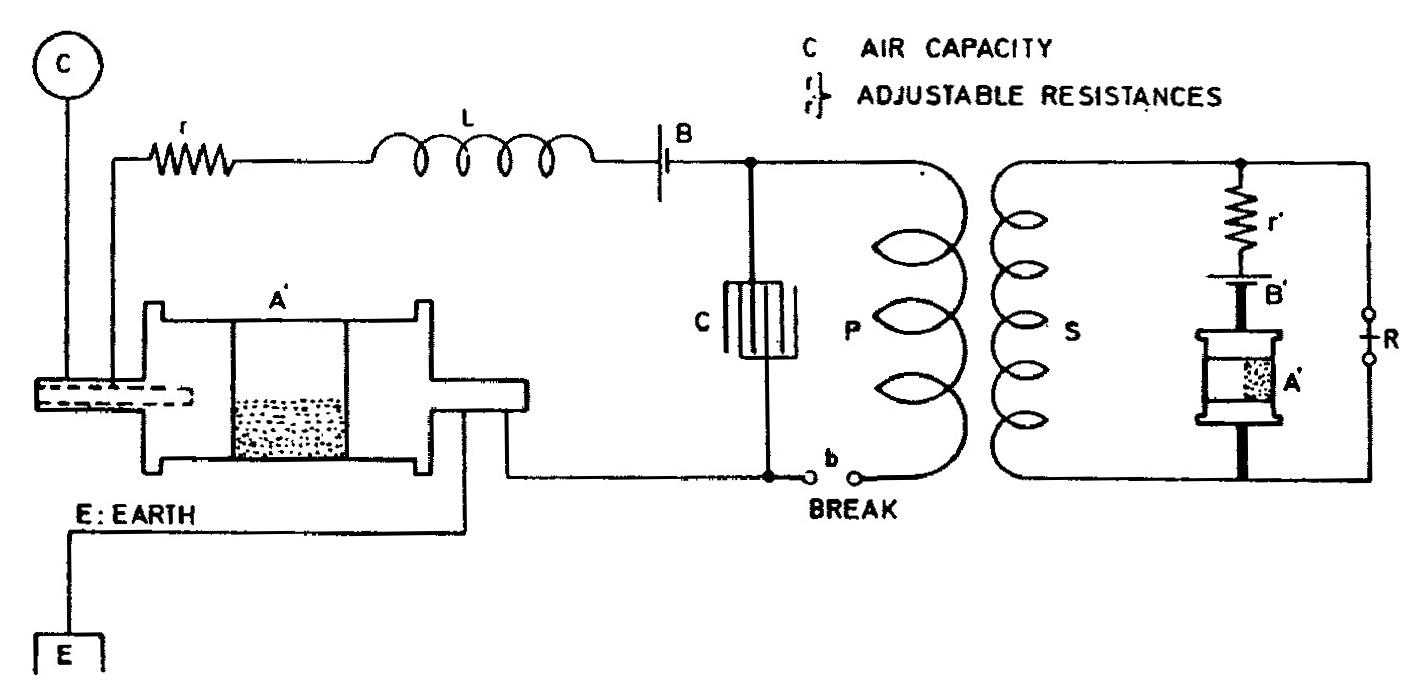
The following arrangement was found particularly efficient in applying the method of magnifying the effects of feeble disturbances by means of a condenser. Two instruments were fixed up in the manner indicated in diagram. A similar plan of connections was used before only the sensitive device A' was differently placed, as it was found to disadvantage. The sensitive devices A and A' were prepared as described on a previous occasion and showed, unexcited, a resistance of over 1,000,000 ohms, but when excited the resistance fell in both almost exactly to fifty ohms. Later, instead of the device A' another was emplo-
109
July 27
In his first arcing-type oscillator for high frequency current production in 1891(4,15) Tesla used a simple "air gap" for the regulation of the oscillator capacitor charging and discharging. Already in the next year he describes several methods for improved operation of simple arcing devices by application of a magnetic field, or an air stream or quick spark interruption and the increase of capacitor charge and discharge frequency. Also he described the advantages of a "divided spark" in multiple small air gaps, when due to increased flashover voltage of a divided arcing device* in comparison with simple arcing device (of the same total air gap length) small gaps can be applied and the losses are smaller.
Fourth method for the achievement of capacitor charging and discharging improved system consisted in the application of various rotating breakers(5).
In patents over the period 1893-1898 Tesla protected several types of breakers or "electrical circuit regulators". It is interesting that all these patents pertain to various types of rotating breakers (with air gap and without). Some of the rotating breakers are protected in an assembly of apparatus for high frequency currents production. Among them are:
- Rotating arcing device (breaker without contacts) in oil made in the shape of a turbine, over which blades the capacitor circuit is made and interrupted, and it rotated by means of oil under pressure(50).
- Mechanical regulators of electrical circuit of the "on-off" type for operation with direct current(51).
- Synchronous regulators of electrical circuits with regulation of the instant of interruption for operation with alternating current sources or without it(52).
- The commutators for alternating "on-off" switching, or connection of two capacitors in Tesla's oscillator primary circuit(53).
In 1897 and 1898 Tesla obtained a number of patents in the field of "electrical circuit regulators. The basic requirement is that these regulators establish and interrupt electrical circuits at the highest possible speed. Further it is required to achieve a great number of operations per time unit. In eight patents(27) Tesla described the design of rotating breakers with conductive or nonconductive fluids. conductive fluid is usually mercury and nonconductive oil. At some regulators the interruption is performed in inert gas under pressure. Extraordinary are the solutions for the achievements of microjets which create a contact with two rotors made of metal for the achievement of two microjets (fluid contact).
Rotating arcing device with two auxiliary gaps as on the Figure is one new solution. Probably additional gaps were applied by Tesla in order to regulate by means of them, the excitation during operation with high voltages. It can be seen from the text that this is possible to achieve when it is mentioned that by means of those gaps it is possible to shorten the supply interval from the network transformer secondary. At the end of his consideration Tesla says he achieved the best results with two rotating arcing devices, (tooth shaped) which rotate in opposite directions. He didn't explain how he chose the number of "teeth" on each rotating disc in order to get the number of interruptions equal to the product of the number of "teeth".
* The total resistance of air gaps connected in series at multiple gap arcing device is smaller than the resistance of usual arcing device of the same flashover voltage.
July 28
This entry provides one of the most detailed descriptions of the receiver with two rotating coherers and a condenser for accumulating the energy from weak signals. At point b the circuit C - P is periodically made and broken and the resulting AC pulses bias sensitive device A' in the secondary. Sensitive device A is still poorly conducting so the charging current of C via damping coil L is small. When an arriving electromagnetic wave reduces the resistance of A, C charges much faster and the voltage induced in secondary S also rises rapidly. The resistance of A' drops rapidly and current from battery B' activates relay R. Judging by Tesla's report, the receiver was very sensitive to distant electrical discharges.
July 28
This is one of the most detailed descriptions of a receiver with two rotating sensitive devices and capacitor for effective accumulation of weak signals. At location 'b' the circuit C - P is periodically switched on and interrupted and obtained alternating current impulses pre-excite the sensitive device A' in the secondary. In the non-excited state, other sensitive device A has high resistance* and therefore the charging current C via ballast coil L is low. When the resistance of sensitive device A reduces, due to action of electromagnetic waves, capacitor charging current C quickly increases and the induced voltage in secondary S is quickly increased as well.
Sensitive device A' resistance is quickly reduced, and current from battery B' acts on relay R which is activated.
Judging on the basis of what Tesla displays, the receiver is very sensitive and reacts to remote electrical discharges.
