Nikola Tesla Books
investigation outside and such use. The synchronized coil was wound in one instance around a drum 10" in diam. and about 4 feet high from the ground and carrying on top a board for placing the box with the instruments and supporting a light rod for air or capacity wire. In another form of apparatus the synchronized coil was wound on drum of 2 foot diam. and 18" high, which was supported on a tripod of photographic outfit.
These two connections illustrated in Diagrams 1. and 2. were found best suitable. The small condenser around secondary s comprised only a few sheets of mica a sufficient to let the currents of a frequency of 50,000 per sec. pass through easy.
Colorado Springs
Sept. 18, 1899
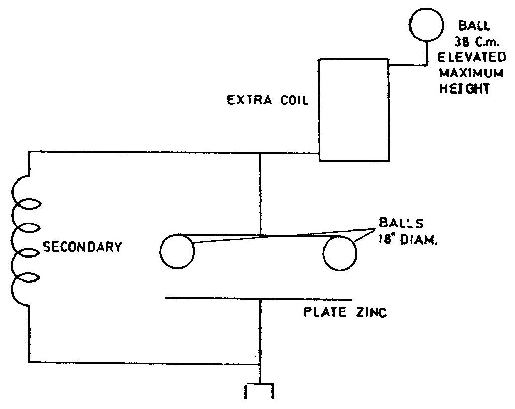
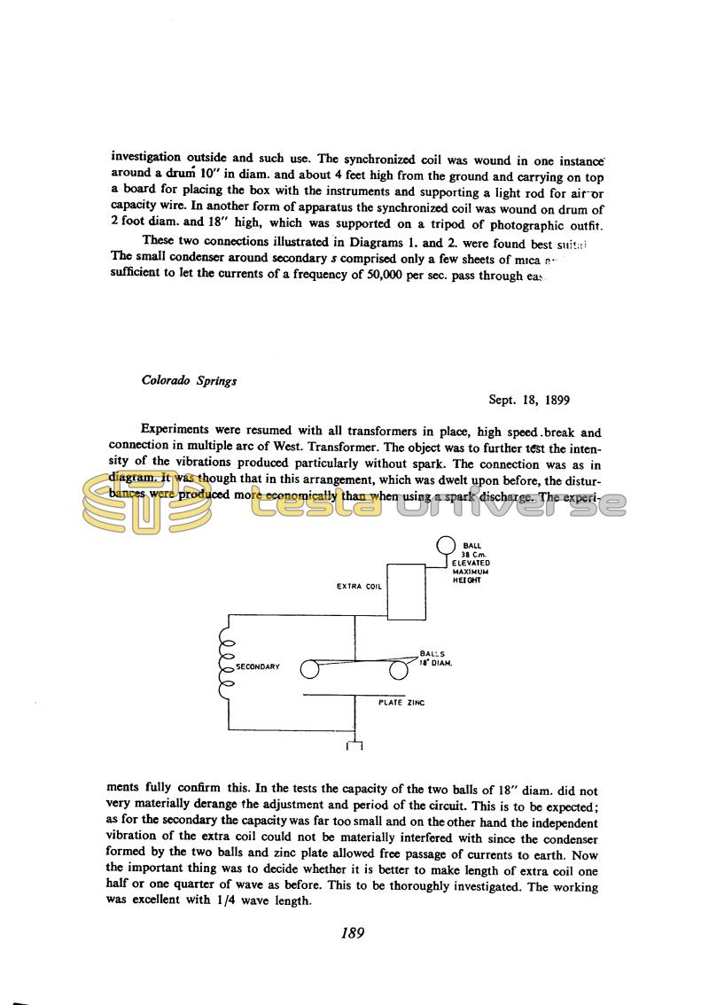
Experiments were resumed with all transformers in place, high speed break and connection in multiple arc of West. Transformer, The object was to further test the intensity of the vibrations produced particularly without spark. The connection was as in diagram. It was though that in this arrangement, which was dwelt upon before, the disturbances were produced more economically than when using a spark discharge. The experiments fully confirm this.
In the tests the capacity of the two balls of 18" diam. did not very materially derange the adjustment and period of the circuit. This is to be expected; as for the secondary the capacity was far too small and on the other hand the independent vibration of the extra coil could not be materially interfered with since the condenser formed by the two balls and zinc plate allowed free passage of currents to earth. Now the important thing was to decide whether it is better to make length of extra coil one half or one quarter of wave as before. This to be thoroughly investigated. The working was excellent with 1/4 wave length.
189
September 18-19
As we mentioned previously, oscillators such as these with which he now experiments do not belong to the classic Tesla oscillators since resonant transformer "additional" coil substantially changes the secondary circuit loading and that will change the manner of oscillation as well. Also, the additional capacitance (as shown on schematics of Sept. 18 and 19 in Figs. 2, 3 and 4) in parallel with the secondary, will change the oscillation spectrum in relation to that which is produced with an oscillator with two oscillating circuits. The connections as on Fig. 5 and 6, given on Sept. 19, could be considered as typical Tesla oscillators with a weak-linked third circuit, which consists of additional coil with capacitive loading.
In that case, he achieved the maximum voltage at the "additional coil" terminals when the natural frequency of this circuit (together with the aerial globe) is equal to the frequency of the strongest component in the oscillator spectrum.


