Nikola Tesla Books
15*
227
Tesla: "System of electric lighting", U.S. Patent 454 622, June 23, 1891, Appl. Apr. 25, 1891, P-208.
"Electric incandescent lamp", U.S. Patent 455 069, June 30, 1891, Appl. May 14, 1891, P-213.
October 17
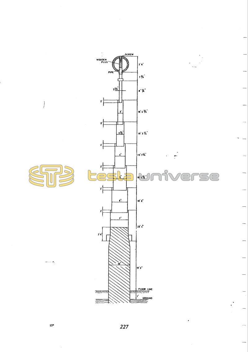
The 122 ft metal pole bearing the 30" ball is the antenna to be seen in the middle of the laboratory on many photographs. The bottom end of the antenna is insulated by a wooden pole. This is a single-pole antenna of small electrical length. At around the highest frequencies which Tesla used the h/λ ratio was about 0.015. The terminal capacity made the effective height somewhat greater than h, but it still remained an electrically short antenna.
October 17
He gives a description of a metal pole 43.3 meters in height with a metal globe 67.2 cm in diameter at the top. This is the aerial which could be seen in the middle of the laboratory on the many photographs. The insulator at the bottom of the aerial is a wood-pole stub. The structure is actually a monopole aerial of small electrical length. At the approximate maximum frequencies with which Tesla operated, the ratio H/λ). is approx. 0.015. Due to the terminal capacitance the effective aerial height is somewhat larger than H/2 but even in that case an electrically small aerial is being questioned. The main reason for the construction of this aerial is the testing of the "vibrations in the ground".


