Nikola Tesla Books
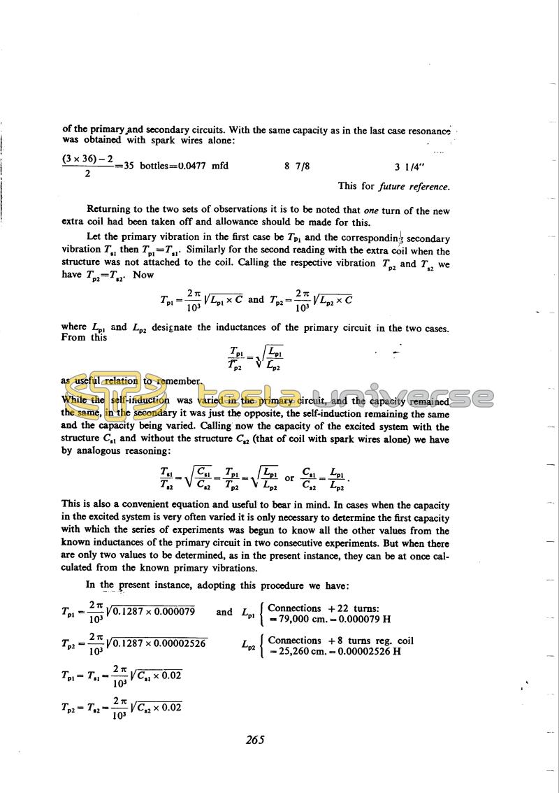
of the primary and secondary circuits. With the same capacity as in the last case resonance was obtained with spark wires alone:
| Capacity in primary exciting circuit total: | Inductance in primary circuit. Turns of regulating coil + conn. | Analyzing spark on terminals of excited coil. |
|---|---|---|
| !$ {{(3x36)-2} \over 2} !$ = 35 bottles = 0.0477 mfd | 8 7/8 | 3 1/4" |
This for future reference.
Returning to the two sets of observations it is to be noted that one turn of the new extra coil had been taken off and allowance should be made for this.
Let the primary vibration in the first case be Tp1 and the corresponding secondary vibration Ts1 then Tp1 = Ts1. Similarly for the second reading with the extra coil when the structure was not attached to the coil. Calling the respective vibration Tp2 and Ts2 we have Tp2 = Ts2. Now
!$ {{T_{p1}} = {{2 \pi \over 10^{3}} \sqrt{{L_{p}}_{1} \times C}}} !$ and !$ {{T_{p}}_{2} = {{2 \pi \over 10^{3}} \sqrt{{L_{p}}_{2} \times C}}} !$
where Lp1 and Lp2 designate the inductances of the primary circuit in the two cases. From this
!$ {{{T_{p}}_{1} \over {T_{p}}_{2}} = { \sqrt{{L_{p}}^{1} \over {L_{p}}^{2}}}} !$
as useful relation to remember.
While the self-induction was varied in the primary circuit, and the capacity remained the same, in the secondary it was just the opposite, the self-induction remaining the same and the capacity being varied. Calling now the capacity of the excited system with the structure Cs1 and without the structure Cs2 (that of coil with spark wires alone) we have by analogous reasoning:
!$ {{{T_{s}}_{1} \over {T_{s}}_{2}} = {\sqrt{{{C_{s}}_{1}} \over {C_{s}}_{2}}} = {{T_{p}}_{1} \over {T_{p}}_{2}} = {\sqrt{{{L_{p}}_{1}} \over {L_{p}}_{2}}}} !$ or !$ {{C_{s}}_{1} \over {C_{s}}_{2}} = {{L_{p}}_{1} \over {L_{p}}_{2}} !$.
This is also a convenient equation and useful to bear in mind. In cases when the capacity in the excited system is very often varied it is only necessary to determine the first capacity with which the series of experiments was begun to know all the other values from the known inductances of the primary circuit in two consecutive experiments. But when there are only two values to be determined, as in the present instance, they can be at once calculated from the known primary vibrations.
In the present instance, adopting this procedure we have:
| Tp1 = !$ {{2 \pi \over 10^{3}} \sqrt{0.1287 \times 0.000079}} !$ | and | Lp1 | { | Connections + 22 turns: = 79,000 cm. = 0.000079 H |
| Tp2 = !$ {{2 \pi \over 10^{3}} \sqrt{0.1287 \times 0.00002526}} !$ | Lp2 | { | Connections + 8 turns reg. coil = 25,260 cm. = 0.00002526 H | |
| Tp1 = Ts1 = !$ {{2 \pi \over 10^{3}} \sqrt{{C_{s}}_{1} \times 0.02}} !$ | ||||
| Tp2 = Ts2 = !$ {{2 \pi \over 10^{3}} \sqrt{{C_{s}}_{2} \times 0.02}} !$ |
265
November 7
Measurement of the capacity of the structure at two frequencies was intended to demonstrate the reduction of effective capacity with increasing frequency. Tesla did in fact obtain a small difference, but it is dubious proof considering the accuracy of the measurements. The frequency difference was quite large, from 50 kHz to nearly 250 kHz (using "extra" and "experimental" coils).
November 7
He measures the structure capacitance with two coils, one is a new "additional coil" (please see Oct. 31). The results are similar to those of Nov. 6. An attempt to measure the structure capacitance at two frequencies was intended to prove that the capacitance is reduced when the frequency is increased. Tesla obtained a small difference but without that it is a reliable proof when we take in account the measurement accuracy. Otherwise the frequency changed substantially; from approximately 50 Hz to almost 250 KHz{during the period of obtaining the measured results with the "additional" and "experimental" coil).

