Nikola Tesla Books
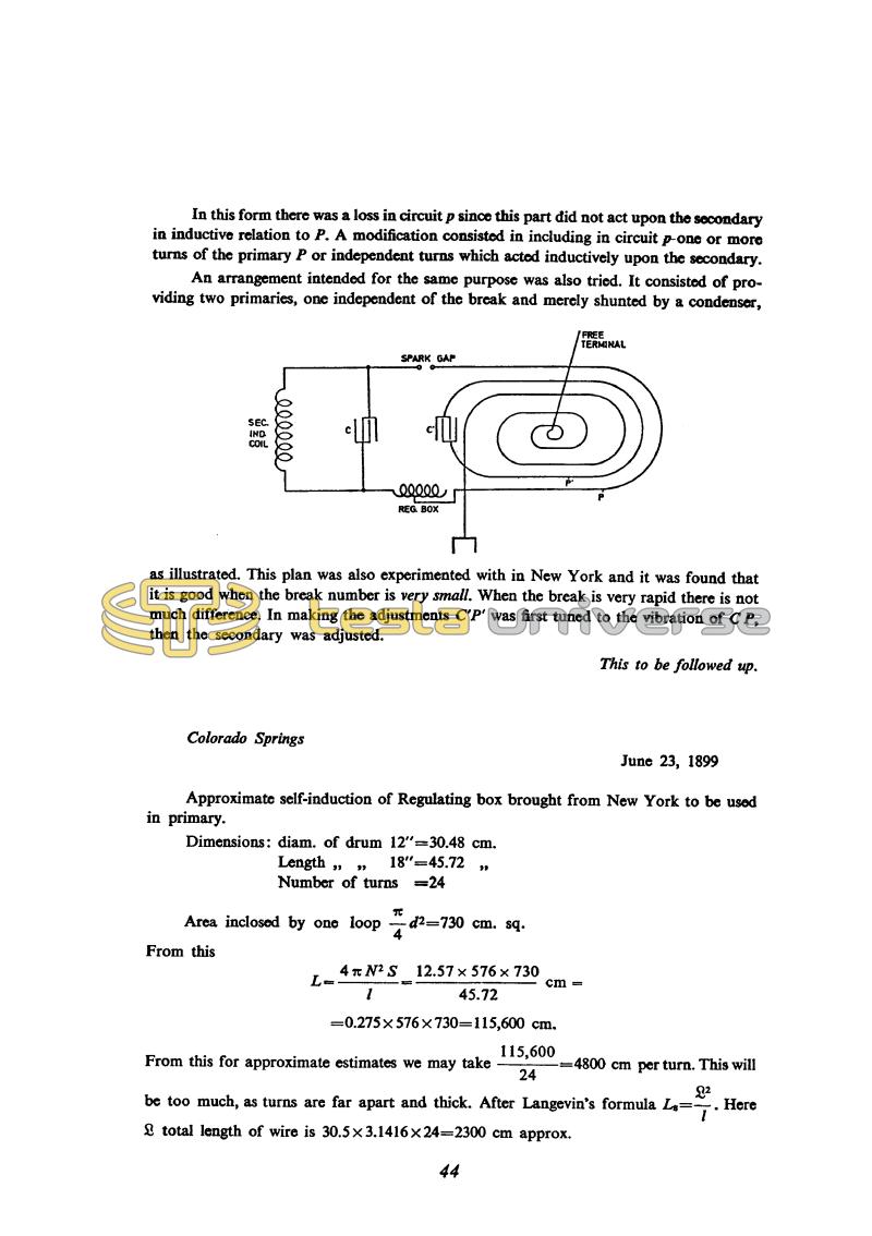
In this form there was a loss in circuit p since this part did not act upon the secondary in inductive relation to P. A modification consisted in including in circuit p one or more turns of the primary P or independent turns which acted inductively upon the secondary.
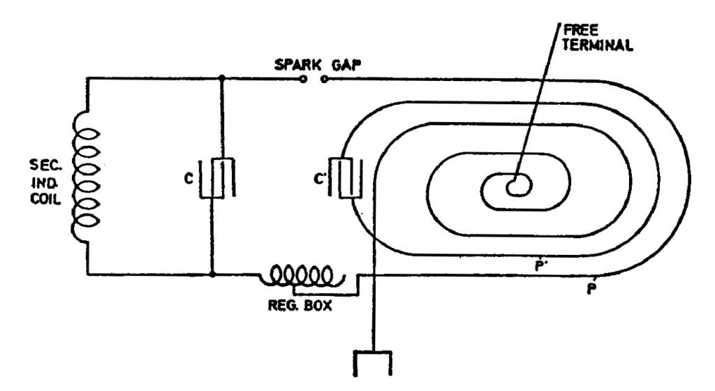
An arrangement intended for the same purpose was also tried. It consisted of providing two primaries, one independent of the break and merely shunted by a condenser,
as illustrated. This plan was also experimented with in New York and it was found that it is good when the break number is very small. When the break is very rapid there is not much difference. In making the adjustments C' P' was first tuned to the vibration of C P, then the secondary was adjusted.
This to be followed up.
Colorado Springs
June 23, 1899
Approximate self-induction of Regulating box brought from New York to be used in primary.
Dimensions:
diam. of drum 12" = 30.48 cm.
Length of drum 18" = 45.72 cm.
Number of turns = 24
Area inclosed by one loop !$ {â¼ \over 4} !$ d2 = 730 cm. sq.
From this
L = !$ { {4 â¼ N^{2} S \over l} = { {12.57 \times 576 \times 730} \over 45.72 } \, cm = } !$
= 0.275 x 576 x 730 = 115,600 cm.
From this for approximate estimates we may take !$ {115,600 \over 24} !$ = 4800 cm per turn. This will be too much, as turns are far apart and thick. After Ls = !$ {£^{2} \over l} !$. Here £ total length of wire is 30.5 x 3.1416 x 24 = 2300 cm approx.
44
June 22
The circuit with two condensers, one being charged from the power supply and the second via a spark from the first represents a modification of Tesla's classic oscillator*. Theory shows that protraction of the oscillation in the primary circuit lowers the efficiency of the oscillator because energy pulses back and forth between the primary and secondary. However, in this circuit protraction of the spark does not have the same effect because while it lasts the primary capacitance is C + C1, but when it stops the capacitance is only C1. Why the sparks in the secondary were stronger with C = aC1, a a whole number, is hard to say without a more exhaustive analysis.
The note at the end of the entry indicates his satisfaction with the results and that he felt it necessary to continue research in the same direction.
June 22
The circuit with two capacitors, of which one is fed from the network, and the other via a spark from the first one, represents the variation of Tesla's classic oscillator*. According to theory the prolonging of the oscillation in the primary circuit reduces the oscillator efficiency due to energy transfer from the primary to secondary and vice versa. On the shown circuit the prolonging of the spark duration does not have the same effect, because during spark existence in primary circuit there is capacitance C + C1, and after spark interruption only C1 remains. Why the sparks in the secondary are more powerful when C = aC1, where 'a' is a whole number, cannot be determined without in-depth analysis.
As proof of better oscillator operation, Tesla accepts longer sparks at the secondary terminals. Sometimes he mentioned other spark characteristics but he assumed that oscillator operates the best when the spark is longest.
According to the schematics shown Tesla experimented with those circuits already earlier in New York. The schematic below with special oscillating circuit represents a system with three linked oscillating circuits, and therefore the oscillation spectrum is more complex. Tesla's remark that the device operates better in such a layout when the number of arcing device interruptions is low (when in the classic schematic with two oscillating circuits the oscillator operation in two oscillating conditions is more emphasized), indicates a possibility of one new approach to oscillator with suitable spectrum even with a relatively good link between exciting and operating circuit.
From time to time Tesla puts special remarks at the end of the notes. On this place, obviously satisfied with achieved results he underlines that research has to be continued in the same direction.
* Several drawings which are given on page 15 are reproduced from original slide found in archives of Nikola Tesla Museum in Belgrade. Four transmitter variations are seen on them which Tesla probably intended to protect by patent.
June 23
The two formulae are in fact identical if the thickness of the wire is neglected, because then
£2 = (2!$ \pi !$rN)2 = 4!$ \pi !$SN2
June 23
For the purpose of primary circuit resonant frequency adjustment he uses the variable inductance*. The value of this inductance he determines by calculation, by means of an equation for an infinitely long coil and another equation which he calls Langevine equation. Actually, these two equations are identical if wire thickness is neglected because then
L2 = (2!$ \pi !$rn)2 = 4!$ \pi !$SN2
In continuation of experiments with oscillator from the previous day, he tests a new combination with auxiliary oscillating circuit formed from one portion of the primary inductance. With this connection Tesla expects that the auxiliary circuit influences the arcing oscillator efficiency. The oscillations in the primary last a short period of time, but oscillation is continued in the regime of linked circuits L1C1 and secondary oscillating circuits. Smaller damping in the L1C1 circuit, then in the primary circuit with the spark is more suitable according to energy balance if the spark lasts a long period of time. For short sparks in the primary, however, it is not certain that this is the only reason for better oscillation operation.
Regulating coil is not shown on the schematic. The regulating coil was probably connected in series in the primary circuit with the other elements.
* This inductance could be seen in photograph no. III.


