Nikola Tesla Books
The object of the considerations which follow is to establish simple relations between the quantities which are known or adopted beforehand, so as to enable the experimenter to construct such coils without previous trials.
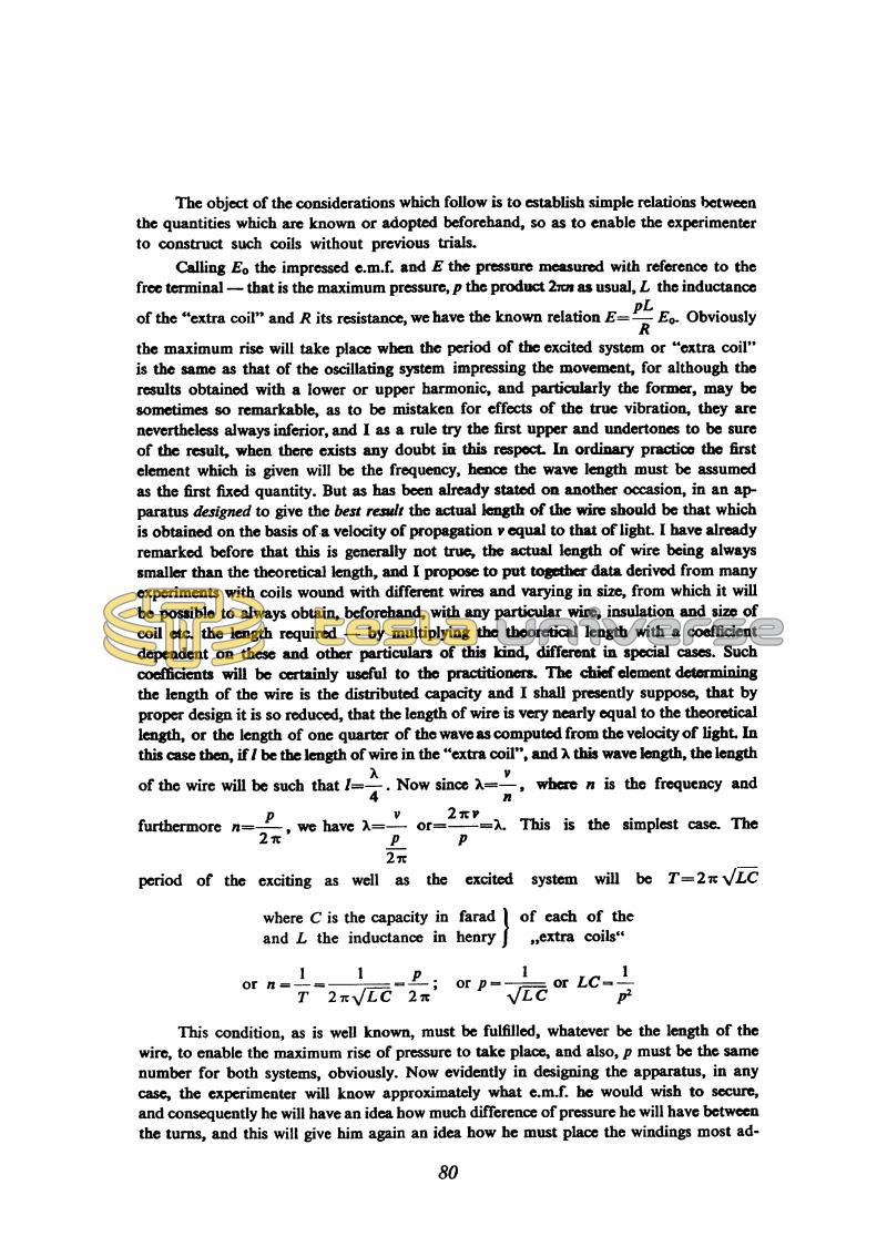
Calling Eo the impressed e.m.f. and E the pressure measured with reference to the free terminal - that is the maximum pressure, p the product 2â¼n as usual, L the inductance of the "extra coil" and R its resistance, we have the known relation E = !$ {{pL \over R} E_{o-}} !$. Obviously the maximum rise will take place when the period of the excited system or "extra coil" is the same as that of the oscillating system impressing the movement, for although the results obtained with a lower or upper harmonic, and particularly the former, may be sometimes so remarkable, as to be mistaken for effects of the true vibration, they are nevertheless always inferior, and I as a rule try the first upper and undertones to be sure of the result, when there exists any doubt in this respect. In ordinary practice the first element which is given will be the frequency, hence the wave length must be assumed as the first fixed quantity. But as has been already stated on another occasion, in an apparatus designed to give the best result the actual length of the wire should be that which is obtained on the basis of a velocity of propagation v equal to that of light. I have already remarked before that this is generally not true, the actual length of wire being always smaller than the theoretical length, and I propose to put together data derived from many experiments with coils wound with different wires and varying in size, from which it will be possible to always obtain, beforehand, with any particular wire, insulation and size of coil etc. the length required - by multiplying the theoretical length with a coefficient dependent on these and other particulars of this kind, different in special cases. Such coefficients will be certainly useful to the practitioners. The chief element determining the length of the wire is the distributed capacity and I shall presently suppose, that by proper design it is so reduced, that the length of wire is very nearly equal to the theoretical length, or the length of one quarter of the wave as computed from the velocity of light. In this case then, if l be the length of wire in the "extra coil", and λ this wave length, the length of the wire will be such that l = !$ {λ \over 4} !$. Now since λ = !$ {v \over n} !$, where n is the frequency and furthermore n = !$ {p \over {2 \pi}} !$, we have λ = !$ {v \over {p \over 2 \pi}} !$ or = !$ {{2 \pi v} \over p} !$ = λ. This is the simplest case. The period of the exciting as well as the excited system will be T = !$ {2 \pi \sqrt{LC}} !$
where C is the capacity in faradand L the inductance in henry } of each of the "extra coils"
or n = !$ {1 \over T} !$ = !$ {1 \over {2 \pi \sqrt{LC}}} !$ = !$ {p \over {2 \pi}} !$; or p = !$ {1 \over \sqrt{LC}} !$ or LC = !$ {1 \over p^{2}} !$
This condition, as is well known, must be fulfilled, whatever be the length of the wire, to enable the maximum rise of pressure to take place, and also, p must be the same number for both systems, obviously. Now evidently in designing the apparatus, in any case, the experimenter will know approximately what e.m.f. he would wish to secure, and consequently he will have an idea how much difference of pressure he will have between the turns, and this will give him again an idea how he must place the windings most ad-
80
July 11
By introducing the additional coil in the oscillator circuit Tesla achieved one modification of his oscillator with resonant transformer. by which means he obtained higher voltages. When these voltages exceeded several hundred thousand volts, he had to carefully lay out the elements, and choose very good insulators. Here the instructions are given how to make the terminals in order to obtain longest and most powerful spark along with delaying the flashover to the instant when maximum voltage is reached (or some desired voltage). He suggests the procedure which enables the voltage measurement by means of metal spheres of various radii. He discusses the disadvantages of this method because the spheres introduce additional capacitance which disturbs the resonance conditions in high frequency circuits.
Tesla considers the additional coil extraordinarily suitable for the achievement of "any" voltage. He gives two wiring schematics of this coil for an oscillator high frequency transformer. He claims that with this coil. considerably higher voltages are achieved than with the secondary in poorer linkage with the primary.
Tesla explains this with the fact that the additional coil is not in an inductive link with the primary, and there is no such reaction in the primary which would dampen the oscillation. He doesn't explain how he imagines this coil to be excited and not to react on the primary transformer secondary to which it is directly connected.
The additional coil description is very detailed. Tesla's wealthy experience in coil design is obvious in its full extent. At the end of his considerations he gives the equation for determination of the number of turns for the additional coil on the basis of operation frequency, wire diameter, separation of windings, and a constant which he determines on the basis of experimental results. He checks the equation on one example and obtains a result very close to the experimental results.

