Nikola Tesla Books
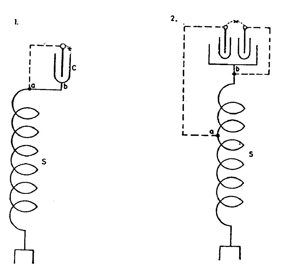
the condenser C, which energy must all be supplied through the secondary, thus producing a large movement in and out of the earth. A modified arrangement is shown in Diagram 2.
An arc may be maintained on the places marked x. Proper rules of tuning are observed to secure best result.
Colorado Springs
July 17, 1899
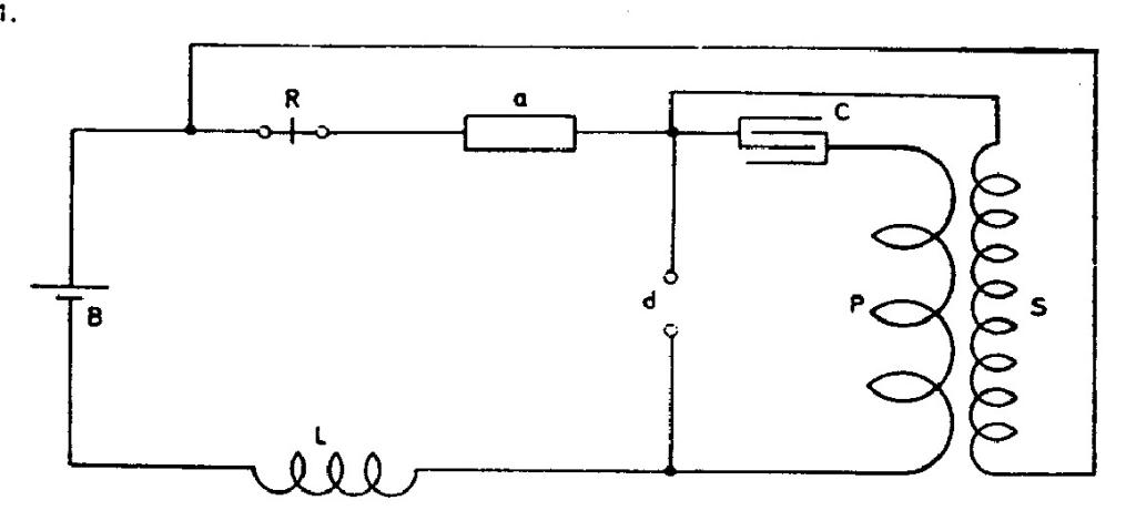
Some arrangements of apparatus experimented with. Modifications of former plans.
Here relay is placed in series with sensitive device but in secondary. In this way relay is not affected by break. The charge of condenser may be regulated by varying L or by resistances in series with L or with S.
89
July 16
In order to achieve the oscillator secondary resonant circuit at relatively low frequency, he looks for a method to achieve large capacitance, but not by means of a large sphere, because that would not be practical. As one possibility he foresees the use of a coil with large self-capacitance, wound by a special technique (therefore, completely opposite from the goal in his previous researches, when he was looking for a method to reduce the coil self-capacitance - e.g. July 9, 10), or by winding a conductive layer of insulation around the wire which will enable "maximum energy concentration" in the coil.
Another method is interesting as an idea, and the essence is that instead of a metal sphere he uses rare gas. The third method has not been sufficiently explained, and the fourth one is based on the use of high voltage capacitor which shunts one portion of the secondary coil.
July 17-18
This is a continuation of the work described in the entry of June 12th, with different combinations of the same components plus relay R for registering the signals received. In all the circuits the sensitive device has an accumulating function. He experimented with different modifications trying to optimize sensitivity and reliability. The circuit in Fig. 1 of July 18th has two batteries, and that Fig. 5 an autotransformer instead of the usual transformer with a primary and secondary.
July 17-18
This is the continuation of July 12 work with new schematics - new combinations of the same components along with the additional relay r. which serves for the purpose of received signals registration. In all circuits the effect on the sensitive device is accumulative. Various combinations with which he experimented represent attempts to find the best elements layout from the viewpoint of sensitivity and reliability. The circuit in Fig. 1, July 18, consists of two batteries, and that in Fig. 5, July 18, consists of an auto-transformer instead of the standard transformer with primary and secondary.


