Plans
Suggestions for Producing High-Frequency Currents and Some of Their Phenomena - Part 1
BY EDWIN F. NORTHRUP AND ELLIOTT WOODS.
Inclination and circumstances have led the writers of this article to construct and play, rather than experiment in a logical and scientific manner, with apparatus of various forms for producing high-frequency currents. As the work has always been fascinating, and often instructive, even if not commercially valuable, it is thought a sort of narrative description of what we have done with high-frequency apparatus and how we constructed it and the phenomena we observed, would not be without interest to electricians interested in the laws and manifestations of electric forces.
The most difficult thing to realize by any artificial means is a strictly constant condition; be it a constant temperature, a constant illumination, a constant tone, a constant current or a constant motion. Nature left to herself tends ever to change, mutations being in general rhythmical. The most striking illustration of this tendency of Nature to a periodic variation which has been recently observed is seen in the action of a Wehnelt interrupter.
When one observes how a violin bow drawn smoothly over the string starts it into vibrations, or how a wet cork rubbed upon a window pane produces a shrill note, or a rotating wheel slightly out of balance sets up violent vibrations, and many other similar phenomena, the action of a Wehnelt interrupter, which acts upon the constantly applied electromotive force to throw the current into rapid pulsations, could certainly have been expected and might have been prophesied.
The movements of electricity in Nature as seen in lightning, in earth currents and in Northern Lights, are fluctuating or oscillating motions. It has been by the exercise of special ingenuity that, through artificial means, direct and constant electric currents have been obtained.
When an electric current flows with perfect uniformity in a circuit the concomitant phenomena are few indeed compared with the phenomena which arise when the current becomes a changing current, varying in magnitude or alternating in direction. A constant direct current is uniformly distributed over the cross-section of the wire, its external inductive effects are nil, and special contrivances must be employed to make evident its very existence. Alternate the current, the more rapidly the more striking the phenomena, and numerous effects external to the circuit are observed. The current is no longer evenly distributed over the cross-section of the wire, but crowds toward its surface until, when the variations are rapid enough, a tube having a thin wall will convey as much energy as if it were a solid rod. With the direct constant current the flow of the current can be calculated by Ohm's law. When the current alternates slowly the calculation can still be made by substituting impedance for resistance, but when the alternations reach a frequency that obtains when the electricity swings freely to and fro in the circuit, exact calculations can no longer be made, as the energy is escaping from the circuit by heat, by radiation and by other paths.
The reason that the study of high-frequency or oscillating currents is so fascinating and instructive lies in the fact that the complexity of the phenomena which are observed forbids and makes impossible prophecies of what will happen by the aid of calculations. As we change the apparatus and vary the conditions under which we work, pleasant surprises are in store and the electrician, if he will make progress, must drop his calculus and become the observant experimenter. The writers have tried a large number of forms of apparatus and different arrangements of circuits for obtaining currents of high frequency of both low and high potential. In this article we shall confine ourselves to describing only one or two forms of apparatus and arrangements of circuits which gave best results.
The experiments of the writers have been confined to the obtaining of oscillating currents by means of the sudden disruptions of an air-gap, though there are other methods by which the equilibrium of the electricity can be disturbed and strong oscillations be obtained. In describing how the writers recently constructed a high-frequency high-potential apparatus, giving a discharge of great volume and over twenty inches in length, the essential features of design and the precautions which must be observed to obtain the best results will be brought out. It should be stated that equally good results might possibly be obtained in a number of other ways, and that the particular method adopted is only that which appeared best to the writers from theoretical considerations and many trials of different forms of apparatus.
It should be stated at the outset, and emphasized, that for obtaining the most powerful and continuous oscillations it is never necessary to resort to any device, such as a magnetic blowout, a blast of air or a mechanical contrivance for making and breaking the circuit, for disrupting the arc which, with improper arrangements, tends to form in the air-gap, weakening or destroying the oscillations. Though there are several methods by which fairly good results may be obtained, by using a source of direct electromotive force, a source of alternating electromotive force of 55 or 110 volts and of about 7,200 alternations is much to be preferred, and for the most powerful effects is necessary. There are five essential parts of a high-frequency apparatus of high potential. First, a variable impedance having as little ohmic resistance as possible and capable of carrying twenty-five or thirty amperes. This is best made by winding No. 8 wire on a core of soft iron wires. This core may be twelve inches long and two to three inches in diameter. The impedance can be made variable by bringing out any number of tapoff points, so that more or less of the turns of the winding may be used. Second, a transformer which will raise 110 volts to about 10,000 or 15,000 volts. This transformer should have a closed magnetic circuit and should be able to deliver at least two-tenths of an ampere from its high-tension winding. Third, a condenser of sufficient capacity and of dielectric strength sufficient to withstand the strain put upon it when a discharge is passing across a parallel discharge-gap of three-quarters to one inch in length. Fourth, a properly constructed double parallel discharge-gap. Fifth, a high-frequency induction coil. The last three of these pieces of apparatus will be more particularly described. Next to the proper proportioning of the apparatus, the most essential and difficult requirement to fulfill is, that all the parts be properly insulated.
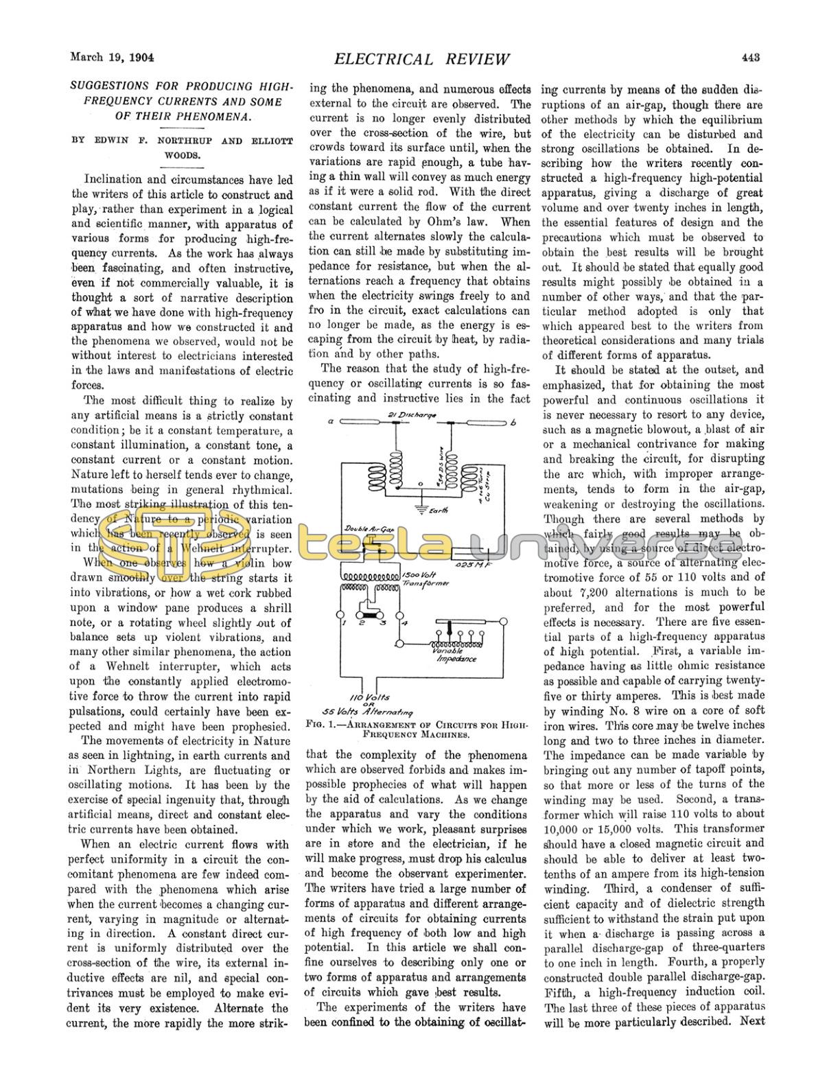
The arrangement of the circuits that the writers finally adopted in obtaining the best results with the high-frequency machine that gave over a twenty-inch discharge is given in Fig. 1. The variable impedance that is shown connected in series with a 15,000-volt transformer performs a very important function. It cannot be replaced successfully by an ohmic resistance. Its action may be described as follows: when the potential has risen to a point where the double air-gap breaks down, the secondary of the transformer becomes short-circuited through the low-resistance path now formed in the double air-gap by the hot gases evolved, and if it were not for the variable impedance a rush of current would flow into the primary of the transformer and a yellow flaming arc would form in the air-gap, still further decreasing the resistance of this air-gap, and prevent the condenser from again becoming charged to a high potential. The impedance prevents this formation of the arc by holding back the sudden rush of current to the primary of the transformer. The disrupted air-gap mends and the potential of the secondary of the transformer again comes upon the condenser, charging it to its full capacity. Curiously enough, varying the amount of the impedance does not appreciably affect the length of the double air-gap that will disrupt. Increasing, however, the impedance beyond a certain point, which is fairly definite, will cause the disruptions of the air-gap, when opened a fixed distance, to quite suddenly cease. When the impedance is thrown entirely out, arcing will generally take place in the air-gap, especially if the capacity of the condenser is small and the transformer a large one, and the oscillations will become very poor or cease altogether. The variation of the impedance through wide limits produces, in a marked manner, a variation of the number of disruptions in the air-gap that take place at each alternation of the electromotive force of the source, this result being made plainly manifest in the varying thickness or volume of the high-tension discharge, as well as in the amount of current which the primary of the transformer will draw.
It will be noted that the primary and secondary of the high-frequency coils of the transformer are divided into two sections, and that the middle points of the primary and secondary are joined together and connected to the ground. The separation of the primary and secondary windings into halves is made chiefly for convenience in mechanical construction and to economize space. Connecting the lower terminals of the two sets of windings together and joining the points united to the ground, is done to protect from the high-tension discharge the insulation between the primary and secondary of the 15,000-volt transformer. If the above precaution be not taken and one side of the secondary of the high-frequency transformer be connected to ground, as is often done in certain experiments with the apparatus, one-half of the potential of the secondary of the high-frequency coil is thrown upon the insulation between the two windings of the 15,000-volt transformer.
Suppose the terminal a were connected to earth and the ground connection omitted, and the primary circuit of the 15,000-volt transformer is separated from ground by a weak insulation, then the current from the secondary of the high-frequency coil would tend to take the following course: from a to ground, from ground to the primary of the 15,000-volt transformer, across the insulation between the primary and secondary of this transformer to the secondary, then through the left-hand winding of the primary of the high-frequency coil to the point o, where the primary and secondary of the high-frequency coils are joined, through the left-hand winding of the secondary and back to a. Thus if the coil gives twenty inches, the insulation between the primary and the secondary of the 15,000-volt transformer may have to withstand a strain equal to a ten-inch discharge of the high-frequency coil. If the ground connection is made at o, it is readily seen that this strain does not come upon the insulation of the transformer.
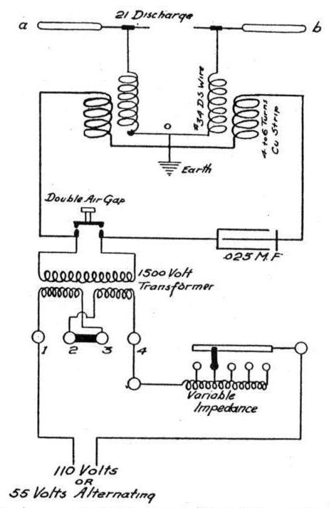
If the primary of the transformer be made with two windings brought out to terminals 1, 2, 3, 4, the two coils of the primary may be connected in series or in parallel, thus adapting it to a 110 or 55-volt circuit. It is not convenient, however, to construct a variable impedance so as to be equally adapted to different voltages. It is not difficult to construct a high-tension transformer for this work, but it would hardly pay one to make this piece of apparatus, since it can be easily obtained in the market. The spark box, and a convenient manner of constructing it, are illustrated in detail in Fig. 2.
In this form of construction the double air-gap is easily controlled and varied in length by turning the insulated handle, which raises and lowers the circular metal disc; this can be done while the coil is in operation without danger of obtaining a shock. If the discharge-gaps are enclosed in a box, as shown in Fig. 2, the noise of the discharge will be lessened. The coil will be generally found to work better after the terminals of the gap and the air on the inside of the box have become heated from operating the coil.
The condenser is most conveniently made as follows: choose plates of the best quality of window glass, fourteen by ten inches, and one-eighth of an inch thick. Tin-foil might answer for the metal sheet of the condenser, but a thin brass or metal sheet is much to be preferred because of its greater mechanical strength and the greater ease with which terminals may be soldered to it. The metal sheet when laid on the glass plate should reach to within one inch on the side margins of the sheet, but be kept two inches from the end opposite to which the terminal is fastened. Thus the effective area of two opposing sheets would be eight by ten inches. The condenser should be laid up in the following order: glass, a sheet of heavy paper, brass sheet, another sheet of heavy paper, glass plate, paper, brass, paper, glass, etc. Half of the brass sheets should have their ends projecting a quarter of an inch from one end of the condenser, and the other half of the brass sheets, alternately placed with the first half, should project in a similar manner from the other end of the condenser. The terminals are, of course, soldered to the projecting ends of the sheets, which are bent down to lie flat and slightly overlap at each end of the condenser. To make this condenser so that it will not break down, it should be laid up under oil, care being taken that no air bubbles get in between the plates. The plates may be held in position by means of a wooden frame, and if the condenser be lifted quickly out of the oil in which it was stacked and placed in its permanent box, and the space between the condenser and its box be filled with melted paraffin, a very strong and dry condenser will be obtained, which will not break down with a one-inch discharge across a parallel gap. The capacity of such a condenser, made of forty plates of glass, is about 0.025 microfarad and is very well adapted for the production of very heavy high-frequency discharges. The writers believe that the particular form given to their high-frequency coil is the most efficient that can be built and that it is somewhat novel, and so we will describe its construction with more detail.
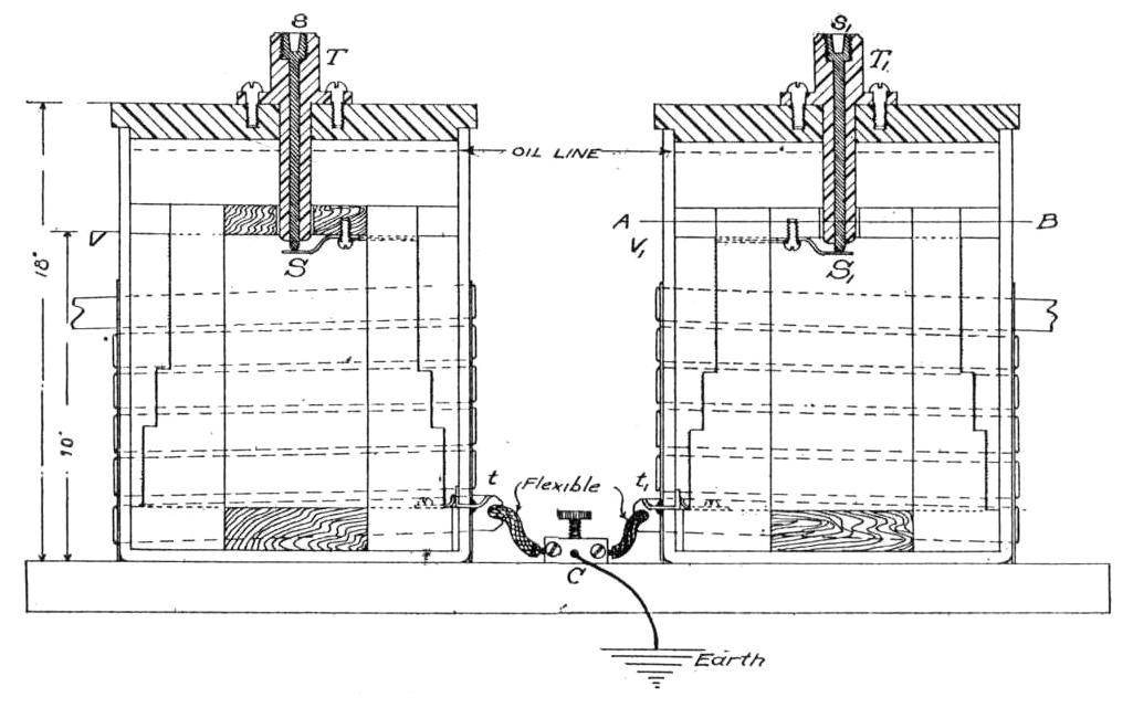
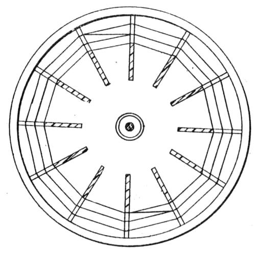
Fig. 3 gives in section and elevation the general form of the design adopted. Fig. 4 is a section on the line AB, of one of the halves of the coil, the two halves being identical. V and V₁ of Fig. 3 are two vessels having the relative dimensions indicated in the figure. These vessels may be of glass, hard rubber or compressed paper. The vessels employed by the writers were made of glass. The primary of the high-frequency coil should preferably consist of about four turns of insulated copper strip wound upon each of the two vessels, the two windings being joined together by a flexible connector C. A convenient way of holding the windings in place is to wind them upon a cardboard cylinder which will just fit over the glass cylinder, the copper straps of which the windings are made being fastened to the cardboard cylinders by being sewed to the cardboard with a strong thread. If the copper strap is insulated with tape or ribbon, the turns can come quite close together; if not insulated they must be kept about one-eighth of an inch apart. By adopting the arrangement shown, the highest possible insulation can be secured for the high-tension secondary winding by filling each of the two vessels nearly to the top with thin paraffin oil. The thinner and better the quality of the oil, the better the insulation secured. If the apparatus is located in a place where there is no fear of fire, the highest possible insulation is secured by the use of kerosene oil. The construction of the secondary coil requires considerable care to obtain the highest efficiency and perfectly secure insulation. The dimensions of the secondary should be proportioned about as shown in Fig. 3. The best way to form a framework on which to wind the wire of the secondary coil is to take two circular boards of hard wood which will just fit on the inside of the glass vessels and make in these boards a dozen or more radial slots one-quarter of an inch wide as indicated in Fig. 4. Hard rubber pieces should then be cut out, having the shape shown in Fig. 3, and these be inserted tightly in the radial slots of the two circular boards. By this means a tapered polygon is formed, upon which the secondary winding may be wound. This winding may be made of double silk-covered No. 34 copper wire, the turns should be laid on evenly and close together, great care being exercised that no single turn shall cross over its neighbors. After the winding is completed, it should be ended off with terminals of heavier wire and the whole be given a thick coating of shellac. This must be allowed to become thoroughly dry before the coil is used. A small hole may be drilled in the bottom of each of the glass vessels V and V₁, through which one end of each of the terminals may be passed and then be fastened to the middle point between the two primaries. The holes can be stopped up with cement so the vessels will not leak oil. Heavy terminals mounted in hard rubber can be fastened in circular covers that rest on the tops of the two vessels and make automatic connections with the two terminals of the secondary by means of spring contacts at S and S'. One suitable form of construction is plainly shown in Fig. 3. One must be cautioned to make the circular covers of the two vessels of some perfectly insulating material, as hard rubber, otherwise brush discharges and streamers will continually pass up the outside surface of the glass vessels, the discharge attempting to take place between the primary and the terminal in the centre of the cover. The terminals between which the high-frequency discharge is to pass may consist of balls or points which can be attached to the tops of the permanent terminals passing up through the centres of the covers. As the two halves of the high-frequency coil are independent of each other, being merely joined together by a flexible connector, the halves of the coil can be moved closer together or farther apart, according to the length of discharge which one wishes to obtain.
(To be concluded.)
Editor note: See part 2 of the article here.