
TCBA Volume 20 - Issue 1
Page 11 of 18
70,000 Volts of power at
500,000 Cycles per second
Experimenting with a "Souped-up"
Tesla Coil
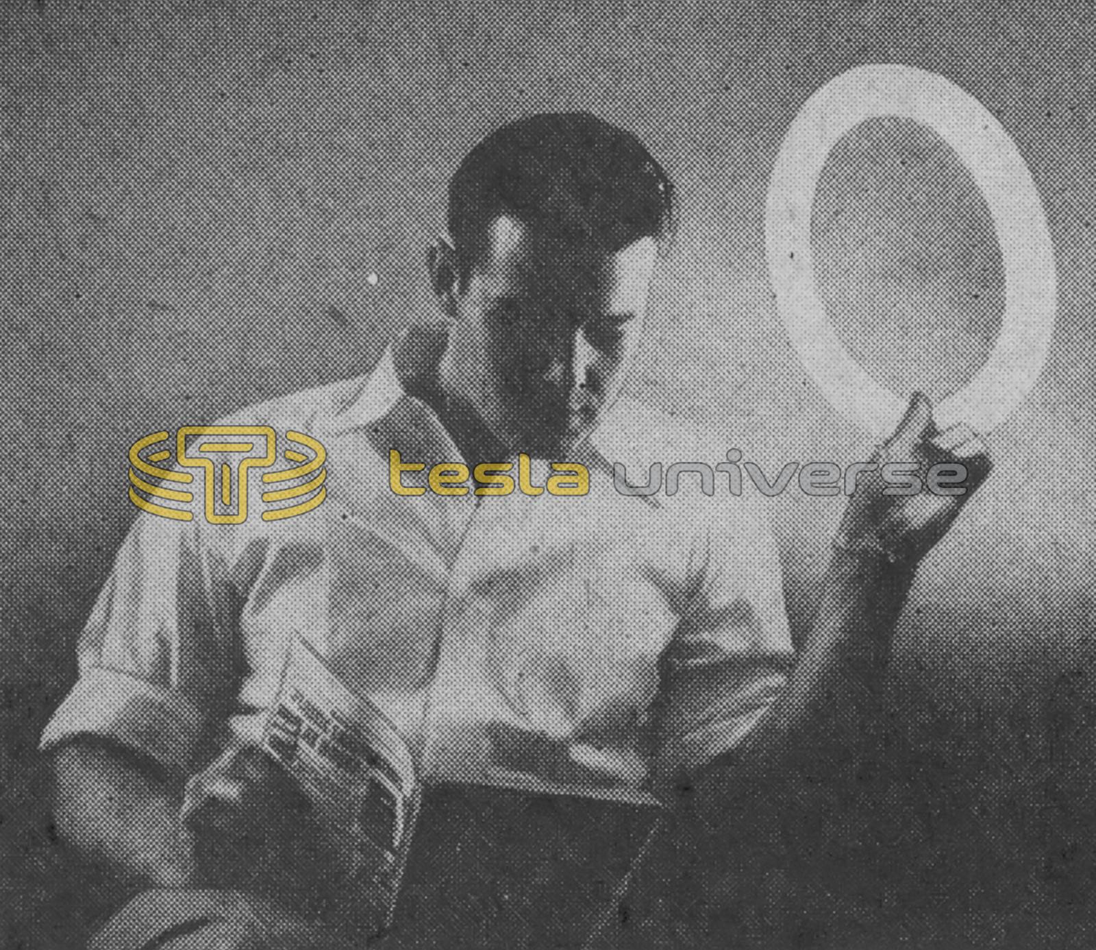
Husky 4-in. brush discharge radiates enough energy with a crackling noise to light Circline bulb in the next room.
By Harold P. Strand
Craft Print Project No. 191
With more power from this bigger Tesla coil, you can perform more of the eerie electrical wonders first demonstrated by Nicola Tesla in 1892. This hotter coil develops 70,000 volts at 500,000 cycles per second frequency and is now on permanent display at the new Museum of Science in Boston, Mass., where it is demonstrated daily. With more potent power, you can perform experiments not open to the smaller coil described on the preceding pages of this handbook.
Even though you'll be experimenting with 70,000 volts, the high frequency (500,000 cps) keeps it harmless. Currents at high frequencies travel over conductor surfaces only, traveling over your skin to ground without damaging any internal organs. Basically this Tesla-type coil uses two vacuum tubes as high-frequency oscillators and a resonant coil tuned to about 500,000 cps. Because of the timing requirements, you must use the values indicated for parts, or the coil will not perform.
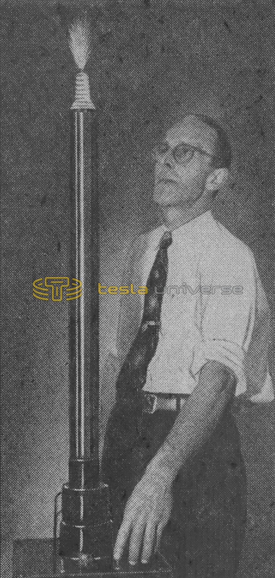
To wind the tall secondary coil, secure the Bakelite 1 3/4-in. tubing (polystyrene is better but more expensive and harder to get). Wind on the 2400 turns of #29 Formex magnet wire and cover the bottom and top leads with varnished tubing. An easy way to wind this coil is to fit wood plugs at each end of the tubing and mount in a lathe. Hand feed the wire and wind the turns closely together. Cover the windings with hot paraffin wax. Wind the primary coil according to Fig. 2. Both coils should be wound in the same direction when mounted in position.
Make up the lower mounting box from 3/4-in. plywood for the base and 1/2 x 1/2-in. angle irons at the corners. The top is a 5/16-in. thick piece of Bakelite. Mount the top and bottom to the corner irons by cutting away one leg of angle and bending other leg over. Bolt through with 6-32 rh bolts. Lay out the bottom piece for mounting the parts (Fig. 8) and drill mounting holes to suit the holes in each part. Form the metal screening to enclose the three sides of the base, but do not fasten it in place until all parts are mounted and wired. Three 6-32 rh bolts along the back of each side hold the screen.