
Nikola Tesla Articles
On the Production of Rotary Magnetic Fields by a Single Alternating Current - Part 1
READ BEFORE THE AMERICAN INSTITUTE OF ELECTRICAL ENGINEERS DECEMBER 19, 1894, BY LUDWIG GUTMANN.
Since the first announcements of Professor Ferraris and Mr. Tesla that rotation can be accomplished by employing two or more alternating currents of displaced phase, the question has been raised by many an engineer as to the possibility of producing a rotary magnetic field by the use of a single circuit, carrying the ordinary alternating current, instead of requiring three or more wires or several independent circuits. So far it has been necessary to construct a special generator armature, the windings of which were rotated in a field of constant polarity, to produce two or more currents lagging in phase behind each other. To use the currents generated for establishing a progressive or rotary field it was necessary to carry as many wires to the place of consumption as currents were employed differing in phase. Six years have passed, and quite rapid progress has been made in various directions. I wish now to bring to your notice a method of generating a rotary magnetic field by a single alternating current or its field without condensers or choking coils. This is accomplished by a device brought out by me some three years ago. Its fundamental principle is hardly as yet appreciated. However, the World's Fair exhibits, as well as literature of late, show that the device has attracted attention, and that several engineers have approached the principle involved.
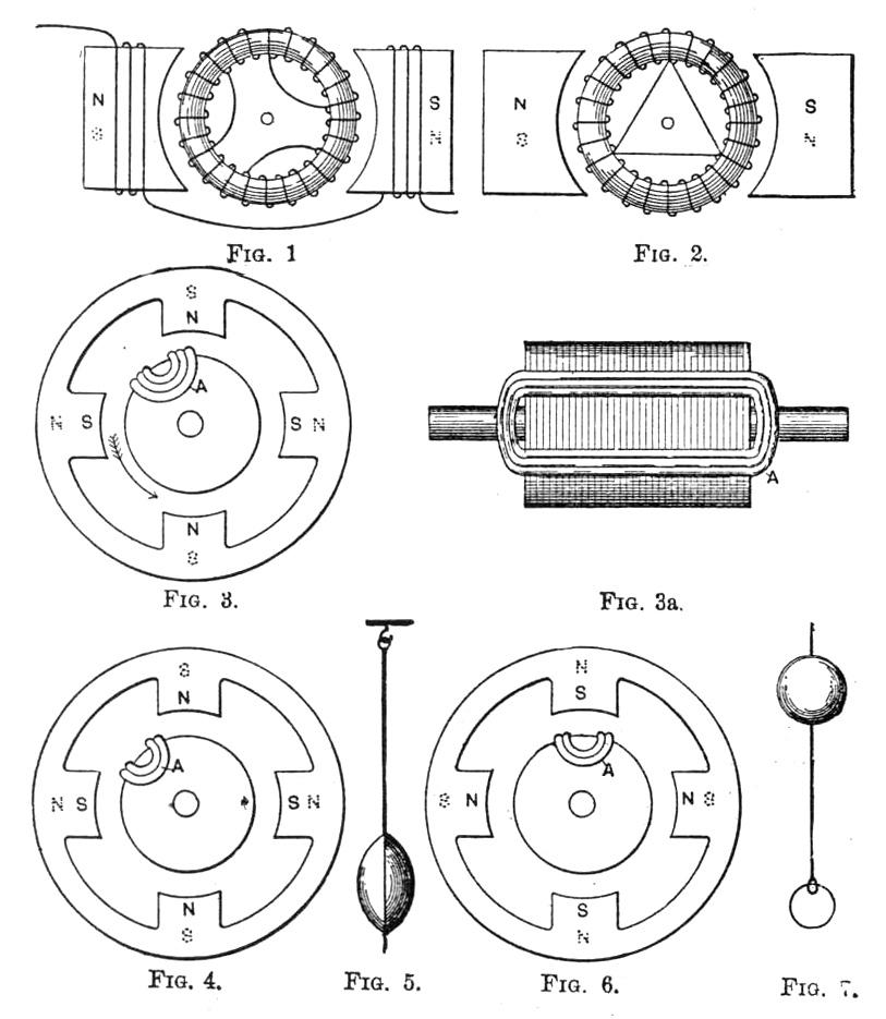
I wish to refer to my motor and especially to its armature, described in 1891. Figs. 1 and 2 show the device. The former is principally used in the American patents, while the latter is given in the English patent of the same year. The novelty of the armature construction lies in a winding containing closed sub-circuits, and another point is that the closed circuits do not coincide in number with the poles of the field magnet. Before going into the action of this device I will mention two simple experiments which are essential in order to understand the operation of this rotary magnetic field system.
If we have a closed coil moving in an alternating magnetic field, or better, between the poles of a field magnet, as illustrated in Figs. 3 and 3a, energized by alternating currents, then the coil A will be repelled from the pole, owing to the secondary field which it establishes, so long as it cuts, or is threaded by the lines of the force of the field. The consequence is that it will rotate and place itself between the north and south pole, Fig. 4, where it reaches a stable magnetic equilibrium, as I like to term it, because in this position it acts like a pendulum properly suspended (Fig. 5). Any motion imparted causes the pendulum to make a few oscillations and come to rest, and similarly any attempt made to move the coil into an energized field will cause it to be repelled, and after a few oscillations it will remain at rest between the poles. It is repelled in either direction, because as soon as it approaches a strong magnetic flux, currents are induced in its windings and create an opposing field. The same coil can be in unstable magnetic equilibrium (Fig. 6), if it stands just in front of a pole, in which position it would act like a pendulum which is balanced with the weight above the point of the support (Fig. 7). Both are in unstable equilibrium; the least motion to the left or right imparted to either will cause them to accelerate in the direction of the impulse, and to assume a position of stability (Figs. 4 and 5). In this position, Fig 4, the coil is therefore currentless. This stable position is the natural position of synchronous motors in operation. If such a synchronous motor is held behind the phase when rotating under load, a heavier current is induced in the spools which accelerate the armature and keep it in step. If, however, the motor runs in harmony, and suddenly a great deal of the load is taken off, then the armature has a tendency to go more quickly, but in this case opposing currents are generated in the windings, which retard the speed of the armature and keep it back, to remain in step or in stability.
Let us look into the device before us and consider first its quality as a motor. Returning to Figs. 1 or 2, preferably the latter, which is simpler and easier to explain, we find that if we send into the field magnet coil an alternating current, the armature will turn through a certain angle and stop. This motion depends upon the position of the three closed coils with respect to the two poles. This same device can itself be self-starting if we make the poles far enough apart and the energizing current sufficiently strong, so that at the initial speed the armature is repelled at a certain rate. This initial speed changes with the number of poles, closed circuits and alternations. Let us take the first case and examine it. If we try to rotate the armature (as I shall call it hereafter) in a field of alternating polarity, we induce currents in the closed circuits, which establish poles, but these poles are alternating in nature, and owing to the motion imparted, and owing further to the permanent connections in the winding, the poles move or travel with the latter. This accounts for the fact that if the field poles are close together the armature consumes power during its rotation through the alternating field; it acts as a dynamo and does not start from a state of rest. If we impart by mechanical means an impulse to the armature, currents are generated whose sum has a variable and principally negative value. The armature makes a few revolutions and places itself in a stable magnetic equilibrium; viz., in such a position, symmetrical if possible, as not to generate any currents, and hence not to induce any reactionary* poles in the core. If, however, we impart to this armature a certain initial speed, which I shall call the critical speed, then it will continue to rotate, with a tendency to reach a certain fixed higher speed. This initial impulse may be given by mechanical or electrical means. I shall not state the results as yet, but prefer to explore the action first, so that the same may be before us in various diagrams, and enable us to make any deduction desirable. First, let us assume that the armature rotates synchronously: it is evident that in order to have an armature with three close-circuited coils, interconnected as shown, rotate in one direction, we must have currents induced whose sum has a positive value; viz., two of the coils must do work, in the same sense, while the third coil is either without a current, or has a smaller current in opposite direction, so that the value still remains positive. For true synchronism a close-circuited coil reaches within a half-period the opposite pole, and consequently our diagram for one revolution would look as follows: (See Fig. 8.)
The three diagrams, a, b, c, show the flow of currents and resultant poles. The close-circuited coil 2, diagram a, is at this moment generating opposing currents to the others; coil 1 is passing just in front of a pole. All three induced currents combined are developing poles as indicated, and rotating the armature in counter clockwise direction. The rotation being synchronous, diagram b shows the position of the armature when the polarity in the field has reversed; diagram c gives the position of the coils after the polarity has changed again. It will be noticed that the original position, as shown at a, has been reached again and that the cycle will repeat itself. Without explaining these diagrams at this point, I wish to bring before you several other conditions, all of which will assist in reaching definite conclusions. Looking at the armature we see that it has a symmetrical winding, and as long as these closed circuits do not coincide with the number of poles of the field magnet (contrary to all synchronous motors built heretofore), other working positions are possible. The operation will take place as long as the sum of the armature currents have a positive value, since as far as the rotation is concerned it is indifferent which of the coils are doing the work. Let us assume that the armature does not run at a synchronous rate, but at another fixed speed which may have a certain commensurable relation to the periods of the exciting field current, which speed I shall call the harmonic speed. Instead of showing the diagram with windings as in the first set, I have simplified them. In the following sets of diagrams, Fig. 9, I assume that the armature, on account of the load or other reasons, cannot reach synchronism, and that at each field reversal the position of the armature with respect to the field is the same, only the coils have changed places as indicated. You will notice that in this set of diagrams the armature, for each half-period, makes one-third of a revolution only; namely, coils 1, 3 and 2 exchange positions with the change of polarity. Let us step at once to another speed (Fig. 10), which you will no doubt admit as possible; viz., let us assume that coils 1, 2 and 3 cannot arrive at synchronous speed, and that coil 2 reaches the position which 1 ought to occupy, it will be seen that owing to the symmetrical position, it is quite indifferent which of these coils arrives at a given position required for harmonic operation. This will be clear to you by referring to the third set of diagrams, Fig. 10.
We are now enabled to compare three sets of diagrams, Figs. 8, 9 and 10. The first set shows for this new type of synchronous motor that at synchronous speed the pole positions in the armature are practically stationary relatively to the coils and core, and rotate with it. The second set shows that during a complete revolution of the armature, the field has reversed three times, that is, an odd number of times, hence, when the armature returns to its original position, after a complete revolution, it finds the field magnetization of reversed polarity. The magnetic field of the armature rotates in the opposite sense, one and a half times per revolution. In the third set, the armature makes but one-sixth of a revolution per half-period, and the magnetic field of the armature in a complete revolution rotates three times in the opposite direction. This statement may be startling, and my argument, so far, may not be entirely convincing, as on close inspection it will be found that the armature poles have to do considerable jumping. I will now explain the performance of the rotary magnetic field of this armature in a four-pole field, where the changes occur far more gradually, leaving no doubt whatever as to the assertion made. Fig. 11 shows diagrams illustrating synchronous speed. By the aid of these four diagrams we can more easily follow the pole position in the armature core, and find them stationary in it. Inspecting now Fig. 12, in which the armature speed is reduced, we are able to obtain a clear picture of the main subject under consideration.
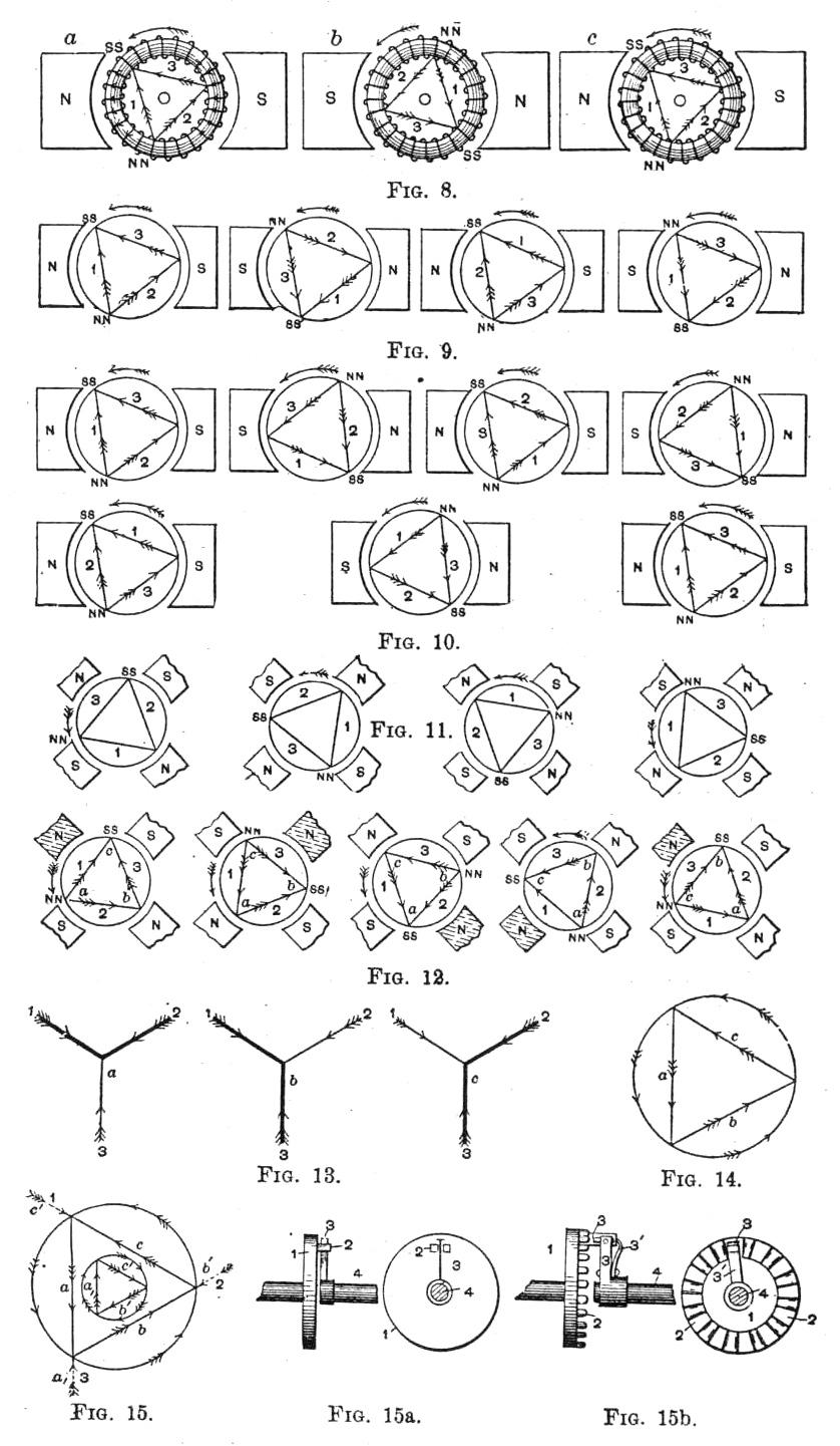
In this set of five diagrams we see five positions, which coil 1, for instance, occupies before it has made one-third of a revolution. Nevertheless, if we now look at the changing pole positions we can readily detect that they are progressively shifting, and we also see that they have made one whole revolution and that in opposite direction to the mechanical rotation, or, in other words, the magnetic field would travel three times around the armature core during one revolution. In all armature diagrams described and to be described the resultant of the magneto-motive forces of the armature currents is given only. To complete the picture showing every one of the component magneto-motive forces acting, it becomes desirable to plot a diagram of force (Fig. 13). These components act like three variable concurrent forces, including an angle of 120 degrees with each other. These forces we may represent as equal, for the sake of convenience, as it does not influence the idea which we wish to illustrate. However, those two forces which are acting in the same direction are indicated by heavier lines.
Plotting the direction of the forces in order, as, for instance, in the last named set of diagrams (Fig. 12), where the coils act in the order 1, 2 against 3; 3, 1 against 2, and 2, 3 against 1, we obtain Fig. 13 for one cycle. The three figures marked a, b and c indicate the direction in which the three forces are acting in the three positions of one cycle or revolution.
By drawing the resultant diagram of force from the predominating forces of each position, we obtain the accompanying figure (Fig. 14). These forces form a triangle, and the rotation resulting may be seen from the direction of arrows on the circumference of the surrounding circle. However, the reactive forces should be considered and represented separately to obtain the true picture, and we have to add them to find the total force applied and the manner in which all the forces are acting. We therefore repeat the resultant diagram (Fig. 14), and add the opposing forces at their proper places. This diagram (Fig. 15) shows that the reactive forces, shown by dotted arrows, also have a common center, and that as regards time of maximum effect, they succeed each other in the direction of rotation of the armature, while they are acting in the opposite direction of the main force. If we now plot a diagram of these reactive forces alone, we obtain the smaller triangle shown (Fig. 15) inside the larger. It will be noticed that rotation is in the opposite direction; or, in other words, that in reality we have, with this disposition, to deal with two rotary magnetic fields in opposite direction; the useful work done will depend on the difference of the angular velocity of these two rotating fields and their relative intensity.
Looking now at the device as a generator (Fig. 12), we can account for the rotary magnetic field because we generate polyphased currents in the coils 1, 2 and 3. They operate together in the following order: 1, 2; 3, 1; 2, 3; 1, 2, etc. If rotated as shown the coils will distribute three-phased currents over the armature, and this will be understood when examining into the flow of currents of the close-circuiting conductors which are here provided with arrows. At this particular harmonic speed it will be further noticed that the simple alternating field of force has the identical qualities as a polyphase energizing field, as the poles in front of the close-circuited coil seem to be traveling (for the armature) in clockwise direction. This is indicated by the shading of the pole of the same sign in front of the coil most powerfully acted upon in the five positions, representing one revolution for the field. The currents displaced in phase cause the armature to rotate harmoniously with the alterations, and prevent the armature from being easily thrown out of step.
(To be concluded.)
Editor's note: See part two here.
* It is well to call the armature poles, due to the armature currents, reactionary poles. The other armature poles are induced directly by the field poles, and contribute nothing to the torque.
