Nikola Tesla Articles
On The Production of Rotary Magnetic Fields by a Single Alternating Current - Part 2
READ BEFORE THE AMERICAN INSTITUTE OF ELECTRICAL ENGINEERS DECEMBER 19, 1894, BY LUDWIG GUTMANN.
(Concluded from page 313.)
Editor's note: See part one here.
Returning once more to the earlier diagrams, Figs. 9 and 10, we see that below synchronism there are two other speeds that are entitled to be called synchronous, because a certain fixed relation exists between the periods of field excitation and armature rotation.
It will be evident that the greater the number of closed circuits, the greater is the number of harmonic or synchronous speeds in which the armature can operate. If the armature contains ten closed circuits, and rotates in a two-pole field, it will be able to generate five currents, lagging 72 degrees behind one another in phase, and would have at least five speeds which are synchronous, and the armature, owing to its peculiar construction, can operate at a slower speed than the synchronous speed as interpreted heretofore.
Looking at the device from a general standpoint, it will be clear that this particular armature construction embodies all the weak points of a synchronous and all the strong points of a polyphase motor. The weak points are:
1. That the machine will not start from state of rest in the form shown, because in Figs. 1, 2 and 12, the coils act on one another differentially and have a variable and negative value; they are in magnetic stability when at rest, hence no rotation can result.
2. The device has a small starting torque when rotated, owing to the differential action of the coils, which cause, with a small number of closed circuits, strongly oscillating or jumping poles until a harmonic speed is reached.
3. The device, when in rotation, is not reversible by simply changing circuit connections.
The strong points are:
1. That the motor develops poly-phased currents in its own windings,
2. That, therefore, it is more difficult to pull it out of step, as it has the capacity to stand, what I would term, magnetic slippage.
Let us assume that a certain coil, which should reach a given point to run harmonically, remains behind owing to a slower motion of the armature; in this event the coil ahead has to perform the function at the expense of a heavier current. The loss of revolutions due to this action may be comparable to the slipping of a belt over a pulley. However, there is also a limit to the slipping. The armature should have some harmonic speed with respect to the alternations. Should it fall below the lowest harmonic speed, then it will come to a standstill just like any other overworked synchronous machine.
Synchronism in a motor means nothing more nor less than a magnetic flexible clutch, which may be represented mechanically as follows:
The old fashioned non-starting synchronous machine having equal armature coils and field poles, can be compared with the arrangement shown in Fig. 15a, giving side view and elevation. The disk 1 is provided with two projections; 2, imparts rotation to shaft 4 by means of the flexible arm, or spring 3, which enables the shaft 4 to be slightly behind or ahead of disk 1. However, if the work put on shaft 4 is in excess of the strength of spring 3, then it will break, and shaft 4 will speedily come to a standstill.
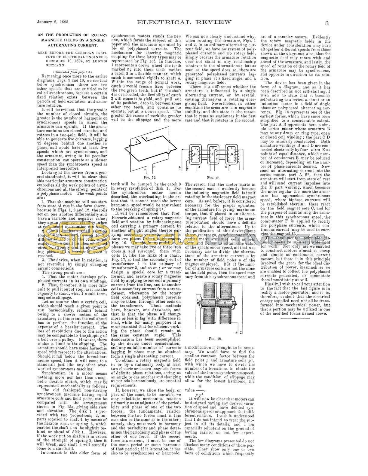
In contrast to this older form of synchronous motors stands the new one, which forms the subject of this paper and the machines operated by bi- or polyphased currents. The mechanism for showing magnetic coupling for these latter types may be represented by Fig. 15b. In this case, 1 represents a crown wheel the teeth marked 2; into these teeth meshes a catch 3 in a flexible manner, which catch is connected rigidly to shaft 4. Within the range of normal work, catch 3 would remain fixed between the two given teeth, but if the shaft is overloaded, the flexibility of catch 3 will cause it to yield, and pull out of its position, drop in between some other two teeth, and continue to operate, but at a slower speed. The greater the excess of work the greater will be the slippage and the more teeth will be jumped by the catch 3 in every revolution of disk 1. For the synchronous motor herein described, the overloading to the extent that it cannot reach the lowest harmonic speed would be equivalent to the breaking of spring 3¹.
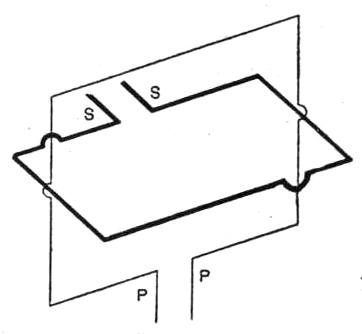
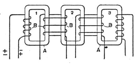
It will be remembered that Prof. Ferraris obtained a rotary magnetic field and rotation by influencing one coil carrying a primary current, by another at right angles thereto carrying secondary currents. Here we have two phases from a single source, Fig. 16. To obtain a multiple of phases we may take two or three iron cores A and surround them with coils B, like the links of a chain, Fig. 17, so that the secondary coil of transformer 1 is the primary of transformer 3, and so on; or we may design a special core for a transformer, and create a rotary magnetic field by applying to one coil a primary current from the line, and to another coil a secondary current from a transformer, whereupon by the rotary field obtained, polyphased currents may be taken through other coils on the transformer. These methods have, however, one drawback, and that is that the phase will change more or less in lag with difference in load, while for many purposes it is most essential that for efficient working the phase should remain at the same constant angle. This desideratum has been accomplished by the device under consideration, and any suitable number of currents lagging in phase may be obtained from a single alternating current.
To obtain a rotary magnetic field in or by a stationary body, at least two electric or electro-magnetic forces of definite phase relations, acting at an angle to one another and changing at periods harmoniously, are essential requirements.
If, however, we allow the body, or part of the same, to be movable, we may substitute mechanical rotation primarily as an adjuster of the periodicity and phase of one of the two forces; the fundamental relation between the two forces must in this case also be the same as in the other; namely, they must work in harmony and the periodicity and phase determines the periodicity and phase of the other of one force. If the second force is a current, it must be one of the same period or some harmonic of that period; if it is rotation, it has also to be synchronous or harmonic.
We can now clearly understand why, when rotating the armature, Figs. 1 and 2, in an ordinary alternating current field, we have no system of poly-phased currents and no rotary field, simply because the armature rotation does not stand in any relationship whatever to the alternations; but as soon as the speed does so, there are generated poly-phased currents lagging in phase at a fixed angle, and a rotary magnetic field.
There is a difference whether the armature is influenced by a single alternating current, or by several, causing themselves a rotating energizing field. Nevertheless, in either condition the armature is in magnetic stability, and this state is the reason that it remains stationary in the first case and that it rotates in the second. The reason that the motor starts in the second case is evidently because the inducing magnetic field is itself rotating in the stationary field magnet core. As said before, it is considered necessary for the proper operation of the armature for giving maximum torque, that if placed in an alternating current field of force the armature rotation should have a definite relation to the alternations. Up to the publication of this device, some three years ago, synchronous motors had as many armature coils as field coils, and hence to obtain the value of the synchronous speed, all that was necessary was to divide the alternations of the armature current n by the number of field poles p of the magnet employed. But if the number of armature coils are not the same as the field poles, then the speed may vary from this synchronous speed and a modification is thought to be necessary. We would have to find the smallest common factor between the field poles p and armature coils p¹, with which we have to divide the number of alternations to obtain the value of the lowest synchronous speed, while the condition of slippage may allow for the lowest harmonic, the value
$$ n \over p \, p^1 $$
It will now be clear that motors can be designed having any desired variation of speed and have defined synchronous speeds or approach the indifferent relation. I wish it understood that I do not intend to treat the subject in all its details, and I am especially reluctant on the ground of having carried on but few experiments.
The few diagrams presented do not disclose many conditions of those possible. They show only one or two facts of conditions which frequently are of a complex nature. Evidently the rotary magnetic fields in the device under consideration may have altogether different speeds from those shown in the diagrams; also, that the magnetic field may rotate with and ahead of the armature, and lastly, the speed of rotation of the rotary field of the armature may be synchronous, and opposite in direction to its rotation.
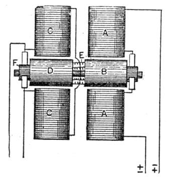
The device has been given in the form of a diagram, and as it has been described as not self-starting, I wish now to state that it becomes self-starting as a series, a shunt or an induction motor in a field of single phase or polyphased alternating currents. Fig. 18 represents one of the earliest forms, which have since been simplified to a considerable extent. The part A B represents here a simple series motor whose armature B may be any drum or ring type, open or closed coil winding; the part C D may be similarly constructed. Both armature windings B and D are connected electrically by four wires E at points of equal distance, which number of conductors E may be reduced or increased, depending on the number of phase currents desired. Now send an alternating current into the series motor, part A B*, then the armature will start from state of rest and will send current impulses into the D part winding, which becomes the more regular the more the armature has approached synchronous speed, where biphase currents will be established thereon in the field magnet core C, and for the purpose of maintaining the armature in this synchronous speed, the commutator F is applied to rectify the polyphase currents, which continuous current may be used to energize the magnet C.
The fundamental principle disclosed opens to us a very wide field for work. Not only are we enabled to construct motors almost as cheap and simple as continuous current motors, but there is in this principle involved the germ for the ideal distribution of power, inasmuch as we are enabled to collect the polyphased currents generated, or commutate them immediately at will.
Finally, I wish to call your attention to the fact that the last figure is in reality a motor-generator, and it is, therefore, evident that the electrical energy supplied need not all be transformed into mechanical power, but that a portion may be utilized in one of the modified forms named above.