Nikola Tesla Articles
The Tesla Two-Phase System - Part 2
EXTENSIVE USE AT THE WESTINGHOUSE WORKS, BRINTON.
The New Plant Fully Equipped with Alternating-Current Apparatus — The Most Important Installation Thus Far Attempted.
BY NELSON W. PERRY, E. M.
Editor's note: See part one here.
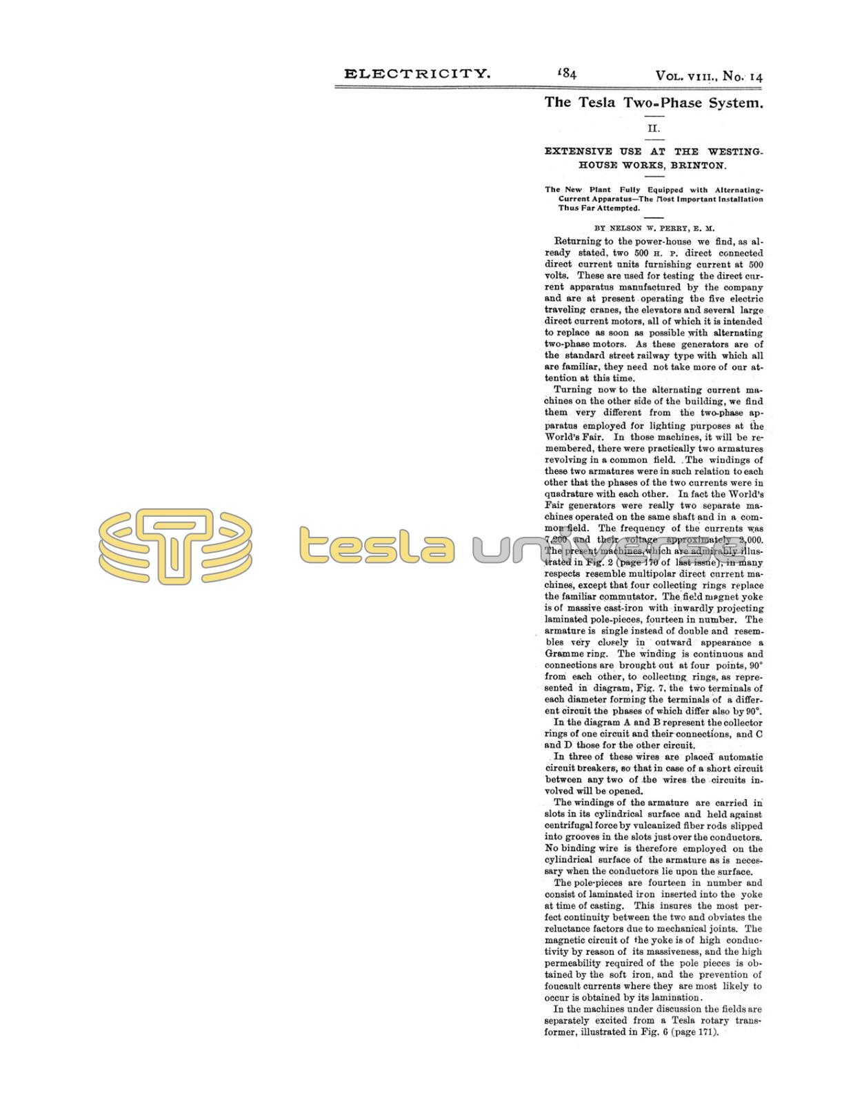
Returning to the powerhouse we find, as already stated, two 500 H. P. direct connected direct current units furnishing current at 500 volts. These are used for testing the direct current apparatus manufactured by the company and are at present operating the five electric traveling cranes, the elevators and several large direct current motors, all of which it is intended to replace as soon as possible with alternating two-phase motors. As these generators are of the standard street railway type with which all are familiar, they need not take more of our attention at this time.
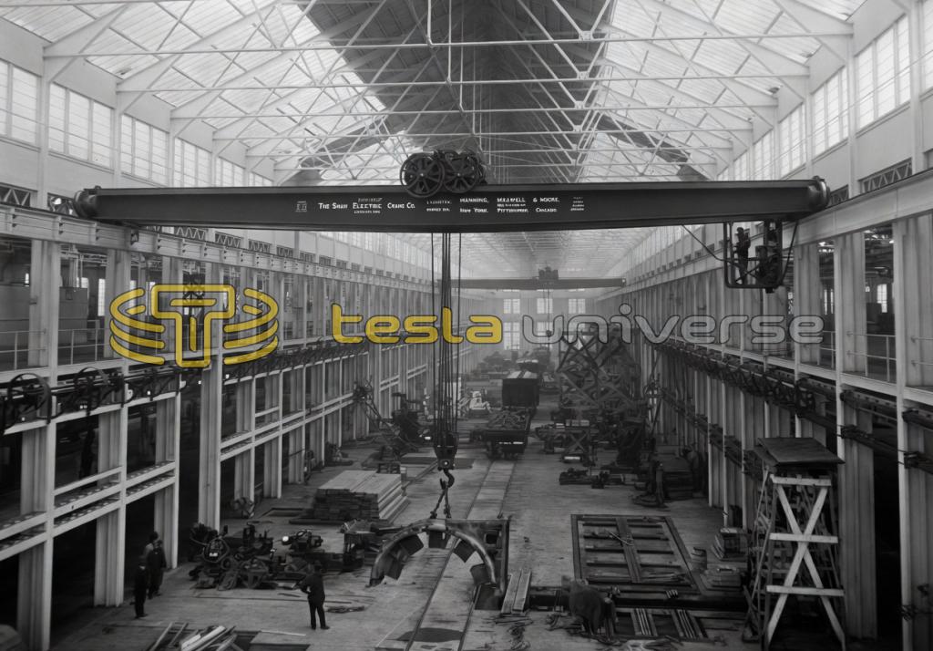
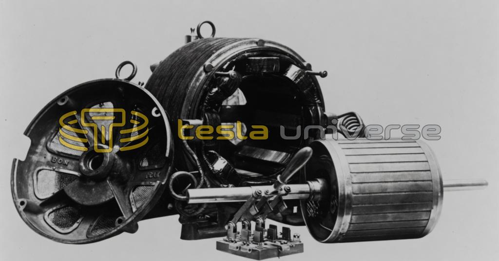
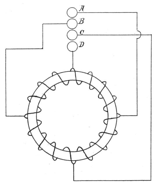
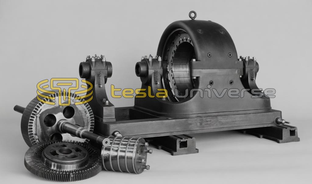
Turning now to the alternating current machines on the other side of the building, we find them very different from the two-phase apparatus employed for lighting purposes at the World's Fair. In those machines, it will be remembered, there were practically two armatures revolving in a common field. The windings of these two armatures were in such relation to each other that the phases of the two currents were in quadrature with each other. In fact the World's Fair generators were really two separate machines operated on the same shaft and in a common field. The frequency of the currents was 7,200 and their voltage approximately 2,000. The present machines, which are admirably illustrated in Fig. 2 (page 170 of last issue), in many respects resemble multipolar direct current machines, except that four collecting rings replace the familiar commutator. The field magnet yoke is of massive cast-iron with inwardly projecting laminated pole-pieces, fourteen in number. The armature is single instead of double and resembles very closely in outward appearance a Gramme ring. The winding is continuous and connections are brought out at four points, 90° from each other, to collecting rings, as represented in diagram, Fig. 7, the two terminals of each diameter forming the terminals of a different circuit the phases of which differ also by 90°.
In the diagram A and B represent the collector rings of one circuit and their connections, and C and D those for the other circuit.
In three of these wires are placed automatic circuit breakers, so that in case of a short circuit between any two of the wires the circuits involved will be opened.
The windings of the armature are carried in slots in its cylindrical surface and held against centrifugal force by vulcanized fiber rods slipped into grooves in the slots just over the conductors. No binding wire is therefore employed on the cylindrical surface of the armature as is necessary when the conductors lie upon the surface.
The pole-pieces are fourteen in number and consist of laminated iron inserted into the yoke at time of casting. This insures the most perfect continuity between the two and obviates the reluctance factors due to mechanical joints. The magnetic circuit of the yoke is of high conductivity by reason of its massiveness, and the high permeability required of the pole pieces is obtained by the soft iron, and the prevention of Foucault currents where they are most likely to occur is obtained by its lamination.
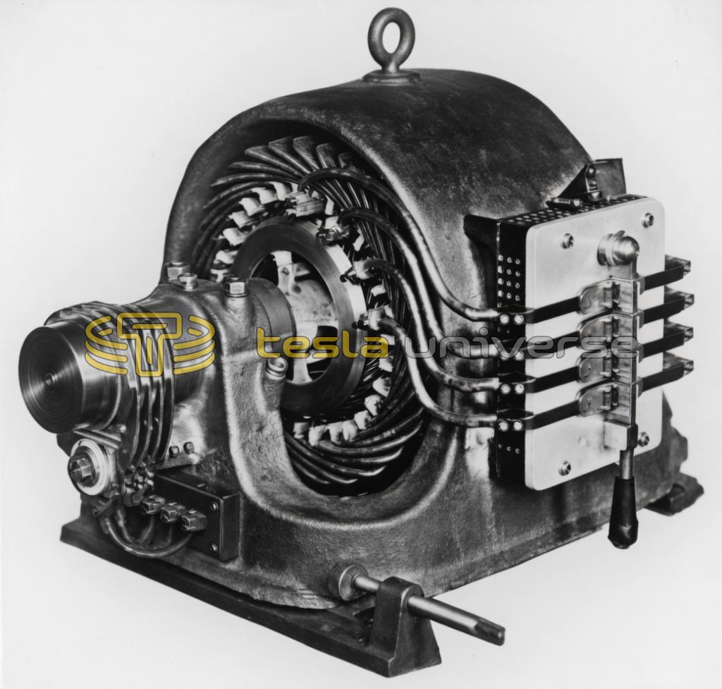
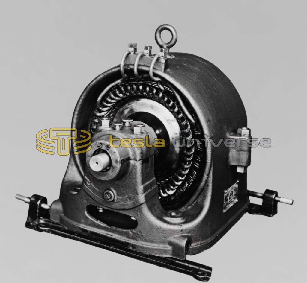
In the machines under discussion the fields are separately excited from a Tesla rotary transformer, illustrated in Fig. 6 (page 171).
This receives the alternating currents at the collector ring end, running as an alternating current motor and transforming them to direct currents which are taken off the commutator end for field excitation.
The two generators run at 220 revolutions, giving currents of 3,000 alternations—the same frequency as is to be employed at Niagara. Since in this installation the greatest distance of transmission is but about 1,100 feet, high potentials were not necessary nor desirable. The voltage employed is therefore only 230 at the generator terminals or about 220 at the motors.
Much has been written about the practicability of coupling alternators in multiple, and while it has been successfully done in a number of cases it has also failed in a sufficient number to give rise in the popular mind to a question as to its practicability. It is of the utmost importance to the central station man that he have the ability to throw units in and out of action, in multiple, as his load changes, for without this ability he must drop out in the race for supremacy. One of the points which the Westinghouse Company wished to emphasize, therefore, was that their two-phase generators could be operated in multiple, and upon their ability to operate in this way they staked the entire success of the new plant. It had not been a question with them, for it had already been demonstrated to their entire satisfaction, but the public required assurance on this point, and the object lesson which these works was intended to afford would have been incomplete had the two generators been employed on separate sets of circuits. They are therefore coupled up in multiple, and during the days when the writer saw them operating were giving a combined output of more than 400 amperes on each of the two circuits. The variation between the two machines was practically negligible, and they seemed to work in parallel in every respect as well as two direct current machines similarly connected are accustomed to do.
Where longer distances are concerned, machines giving higher potentials would be employed and step-down transformers used at the point of distribution to bring the voltage down to that suitable for motor work or lighting; or if very long distances were involved, requiring higher potentials than it would be desirable to generate directly in the armature, these same machines generating 230 volts could be used, step-up transformers employed at the power station to raise the voltage to that required for economical transmission, and step-down transformers at the point of distribution employed as before to reduce the pressure to the requirements of service.
The simplicity and efficiency of the closed magnetic circuit transformer are too well known to require remark here further than to say that they are the most efficient transformers of energy known to man. So high has this efficiency been for several years past that little improvement seemed possible or even desirable in this direction. There has been room for improvement, however, in methods of insulation against the increasingly high potentials now being used and in the dissipation of the heat energy which constitutes inevitable losses in the transformer. Theoretically a transformer working with a hot core and a cool coil would be the most efficient, but these two conditions are incompatible. They have been partially realized, however, in the Westinghouse transformer, which is illustrated in Fig. 8. This photograph shows very clearly the method of building up the laminated core around the coils adopted by this company, but the main feature to which it is desired to call attention at this time is the spreading of the ends of the coils after they come out of the iron, which affords a much better opportunity for the dissipation of the heat energy developed in the coils than any other method thus far suggested which does not at the same time dissipate the heat from the iron as well.
Still another essential to a good transformer or converter, as the Westinghouse people call it, is that it shall be proof against the breaking down of the dielectric. Where comparatively low potentials are concerned, it is not difficult to insulate against them, but when extreme pressures such as long-distance transmissions require are used, the insulation against these pressures becomes a question of the utmost importance. Tesla has shown that the air itself is a most fruitful cause of discharge across either from static or dynamic charges, and that if this be removed many of the difficulties of transformer insulation are also removed. The Westinghouse Company, therefore, exclude the air from the transformer chamber by utilizing a fluid dielectric, which has the further quality, not possessed by solid dielectrics, of repairing itself in case it does at any instant break down. The transformer shown is the latest type of the oil transformer now manufactured and used on high-potential circuits. As will be observed, no attempt is made at high insulation in the winding of the coils, they being simply wrapped in untreated cotton tape. The transformer, however, when ready for use is simply immersed in an oil bath, the air driven out as far as possible and then connected up for service.
The Westinghouse Company was the first to appreciate the possibilities of the alternating current in long-distance transmission, and when the inventions of Gaulard and Gibbs had placed it on a commercial basis, they at once procured the exclusive right to their use. They have therefore been the pioneers in this class of apparatus, and while the system of to-day bears little resemblance to that elaborated by Gaulard and Gibbs, the system of transformation is based primarily upon the fundamental patents issued to those two gentlemen. Many other fundamental patents bearing upon this important field were also early acquired, among the most important of which are the Tesla polyphase patents, which it is claimed completely cover the whole field of polyphase transmission and distribution and which will find their highest and most extensive application in the great Niagara scheme.
The Tesla polyphase patents upon which the Westinghouse Company base their claims of ownership in this field are the following:
May 1, 1888, Nos. 381,968 — 381,969 — 381,970 — 382,279 — 382,280 — 382,281, — 382,282.
October 2, 1888, Nos. 390,413 — 390,414.
October 9, 1888, Nos. 390,721 — 390,820.
April 16, 1889, No. 401,520.
June 25, 1889, No. 405,858 — 405,859.
December 3, 1889, Nos. 416,191 — 416,192 — 416, 193 — 416,194 — 416,195.
December 31, 1889, No. 418,248.
March 25, 1890, No. 424,036.
August 5, 1890, Nos. 433,700 — 433,701 — 433,702 — 433,703.
January 27, 1891, No. 445,207.
June 30, 1891, No. 445,067.
September 22, 1891, No. 459,772.
December 8, 1891, No. 464,666.
Making twenty-nine patents all told, which the company believe completely cover the polyphase field so far at least as it has been developed.
It is not to be supposed, however, that any one mind has contributed all that goes to make up the completed commercial system of to-day. Many minds indeed have contributed to the perfected system as exemplified in the plant under discussion, and while, if we were to confine ourselves strictly to this particular plant, we would necessarily pass lightly over some of these features, or not mention them at all, the description of the system as a whole would be incomplete. At the risk, therefore, of seeming a little prolix some of the more important accessories will be referred to.
Where lights are to be supplied as well as power, it is of the utmost importance to have means at hand by which the potential on the various circuits may be regulated so as to compensate for the change of losses due to variations in load. The voltmeter as usually employed in the generating station indicates only the pressure at the generator terminals and not that at the point of consumption where the variable effects of drop are encountered. In ordinary practice it has been customary to bring back small pressure wires from the points of distribution, by which means the pressures at those points were indicated and the proper regulation indicated to the station manager. A method of equalizing the pressures among a number of distribution points, often resorted to, has been that of connecting them all together with equalizing wires. Both of these methods are cumbersome and expensive, and have been discarded by the Westinghouse Company. In their places have been substituted the following arrangements:
The voltmeter is supplied by the secondary of a small converter, usually reducing in the ratio of 30 to 1 where the initial voltage is 3,300, or in a greater ratio if higher. In the voltmeter circuit there is placed a compensator. This is shown in Fig. 9, and consists of a small transformer with its primary in series with the main circuit and its secondary in series with the voltmeter circuit, and connected in such a way that the compensator pressure to the main current opposes the voltmeter pressure to an extent proportional to the loss in the conductors. The voltmeter by this arrangement, therefore, indicates the potential — not at the station, but at the point of distribution.
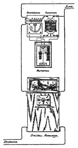
Now as this pressure varies it becomes necessary to have some means of correspondingly varying the station pressure. If there were but one circuit extending from each generator, this would easily be accomplished either by varying the field excitation or the speed of the armature, but in practice there are usually a number of circuits extending from each machine in each of which a different compensation is required, and the methods referred to would not be applicable. To meet such cases resort is had to the Stillwell Regulator, represented in diagram in Fig. 10.
THE STILLWELL REGULATOR.
The great value and importance of this instrument as a part of the modern complete central station equipment has been demonstrated beyond question. The principle of the instrument — as beautiful as it is simple — is that of induction. For this reason no similar device can be operated from a direct current system. It consists primarily of a converter, suitably designed, with secondary coil adjustable in length, i. e., with connections brought out from different parts of the secondary coil to a multipoint switch. By means of this switch the whole or any part of the secondary coil may be thrown in series with the main circuit, thus adding to the initial primary potential of the circuit the additional potential of the secondary coil, or a part thereof. Within the limits of the voltage thus added the potential of the supply circuit is, therefore, subject to the most delicately shaded adjustment, independent of whatever may be the potential at the alternator terminals. Consequently, it is the practice to have several supply circuits taking current from the same generator, and hence, of course, they are at absolutely the same potential. Although each circuit may be operated at a different percentage of loss, by the use of the Stillwell Regulator all lamps will be maintained at a uniform voltage and brilliancy. The attachment of a double-throw switch makes it practicable to reverse the action of the regulator and decrease instead of increase the initial potential. This may be frequently done to meet local conditions, and is an additional convenience.
It will be noted that this instrument simply increases the electromotive force in the circuit by a few volts. To do this it is necessary to transform but a small portion of the electrical energy passing through the regulator. The efficiency of conversion of this fraction of energy is easily 95 per cent., and it is therefore evident that the loss of energy in the regulator will be but an extremely small percentage of the total energy of the circuit. For example, at full load a 100 ampere regulator, designed to raise the initial potential 10 per cent., would receive at the terminals of its primary coil 10 amperes at 1,000 volts, and at the terminals of its secondary coil would deliver 100 amperes at 100 volts, less any losses suffered in conversion. These losses, being the same as those of a standard converter of equal capacity, aggregate not to exceed 5 per cent., i. e., 500 watts. The total energy supplied to the circuit by the generator being 110 amperes at 1,000 volts, i. e., 110,000 watts, the percentage of loss is therefore .00455, or less than 1/2 per cent.
The extreme flexibility supplied by the use of the regulator is illustrated by an example which occurs almost daily in practice. Let us assume a small station operating under ordinary conditions with, say, a loss of 2½ per cent. in its feeders and 1 per cent in its mains, the territory supplied being within a radius of one mile from the station. Let us further assume that there is a point two and one-half miles distant where an additional 500 lights can be secured. It would evidently not pay to erect a special alternator to supply this number of lights, and yet to supply them from the same alternator sufficient additional copper must be put into the new circuits to reduce the losses over the greater distance to those already incurred in the shorter circuits. This also would prove uneconomical and the station manager would find himself confined to a choice of three undesirable methods: 1st, to install a new alternator for the 500 lights; 2d, put in a sufficiently heavy wire to maintain the same loss at the greater distance, and 3d, abandon the idea entirely of supplying the new customers. I do not know whether dilemmas usually have three horns, but this one seems to have and they all promise to be equally uncomfortable to sit upon. The regulator, however, comes to the station manager's assistance in this way: Assuming an average of 1/2 ampere in the primary line for every 16 c. p. lamp on the secondary circuits and a 10 per cent. Stillwell Regulator to be attached to the new circuit, it is immediately possible to raise the initial electromotive force 10 per cent. above the electromotive force of the other circuits supplied from the same dynamo, and to therefore allow an additional loss of the same amount on the line. The line cost for supplying these lights by this means (including the cost of the regulator) would be only about one-third what it would were the extra copper otherwise required employed. It also effects economies in operation and renders possible much better service by placing in the hands of the station manager a most perfect means of independent regulation of the various circuits extending from the same dynamo.
In the regulators as now put on the market, the secondary is divided into small sections, each of which has an electromotive force equal to 1 per cent. of the primary. Any number of these sections may be placed in series with the supply circuit, and thus with standard apparatus the variations in pressure at the point of distribution may be compensated for through all variations in load within less than 1 per cent.
All long lines of overhead wire, and particularly such as traverse mountainous sections, are subject to violent atmospheric conditions which if not provided against in some efficient manner are liable to result in the destruction of the machinery at both ends of the line. The popular belief is that these destructive effects are due to lightning, but while they are apt to occur most frequently in sections of country where severe thunder-storms prevail it is doubtful if the lightning itself ever, or at least frequently, actually strikes the wires. The so-called lightning strokes on circuits are now known to be chiefly inductive effects, due to sudden changes of potential of the earth or clouds due to lightning flashes occurring not necessarily in the immediate proximity of the circuits, but which by inductive effects set up electrical surgings in the wires. These surgings if they reach the transformer or dynamos are liable to cause disruptive discharges across the insulation which may lead to its destruction. It is not the disruptive discharge, however, that does so much damage, as it is the dynamo current which, having had this path opened to it by the disruptive discharge, follows it. An effective lightning arrester, therefore, has two distinct offices to fill: 1st, to offer an easier path for the surgings than that through the coils of the machinery whereby it may be drawn off the line, and second, to prevent the passage of the dynamo current over the same path that the disruptive discharge has opened for it. The old idea was that the first of these functions was fulfilled when a grounded conductor was separated by a short air-gap from the circuits to be protected, and the second by providing some mechanism, either mechanical or magnetic, by which the arc which followed might be broken instantaneously and the normal air gap re-established for subsequent protection. Experience has taught, however, that these electrical surgings do not seek to leave the wires with equal force at all points and that they will frequently pass by a number of short air gaps and then find the ground through a much longer and apparently more difficult path. The reason for this is now well understood and is implied by the name by which I have described them, viz., surgings. If an air gap be provided where the crest of the wave happens to be, a discharge will take place, whereas similar air-gaps, or even shorter ones, would be passed by by the same surging if they happened to be situated at any other point than where the crest happened to be found.
Mr. Alexander Jay Wurtz of the Westinghouse Company has made, under their auspices, a very exhaustive study of the phenomena of so-called lightning discharges on overhead circuits, and has discovered a method by which the lines are afforded almost absolute protection from these dangers. The basis of this discovery is that of a non-arcing metal which, when employed as the terminals of an air gap, permits the disruptive discharge to pass but immediately extinguishes, by virtue of some inherent quality of the metal itself or its vapor, the arc that would otherwise follow. In his completed arrester he employs seven cylinders of the metal — each one inch in diameter, and three inches long. These are mounted side by side, separated from one another by 1/4 of an inch. The central one is connected to the ground while the two outside ones are connected to the two sides of the circuit. With these metals and this arrangement it has been found impossible to start and maintain an arc when they are separated by an air gap of this size, but strange to say, where the gap is longer — say half an inch — the arcing is said to be very vicious. In recognition of the value of this discovery of non-arcing metals and their application to the protection of circuits, the Franklin Institute of Philadelphia awarded to Mr. Wurtz the John Scott Legacy premium and medal. These lightning arresters are placed at such frequent intervals along the line that some one or more of them is sure to be in the proper position to draw off the charge at the crest of the wave. The arresters are also placed in the stations at both ends of the line. As showing the frequency of these discharges in some localities, an instance is cited in the experience of a line at Telluride, Colorado, when forty-two discharges of the lightning arresters were observed in as many minutes, any one of which might, if not thus provided for, have damaged or destroyed the machinery at one or the other end of the line.
The above digression has been indulged in to call attention to some of the accessories to a transmission plant installed on the Westinghouse system. This is scarcely pertinent to the subject in hand, but we may consider that the Westinghouse shops are located at the further end of a long line of transmission, and that the high voltage transmission currents of 5, 10 or 20 thousand volts have been transformed down in the power house to 230 volts for distribution, the dynamos previously described being simply replaced by step-down transformers, and we have the conditions exactly as they would be if the shops were actually hitched on to Niagara or any other distant source of power. The switchboard would remain as it is, and from it would run, as they do now, the four circuits — two for each of the two-phase currents.
At Pittsburg these wires are carried overhead on insulators to the various buildings where power and light are required.
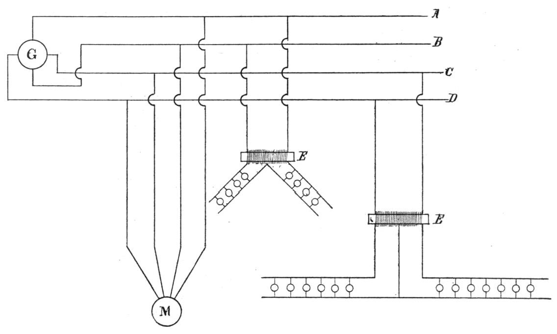
Fig. 11 shows the methods of distribution and the manner of taking current off from the circuits both for motors and light. It will be observed that the lights are taken off of both circuits indiscriminately. Usually, it would be better to divide the lights about equally between the two circuits, for the reason that where all the motors used are two-phased motors, as in this establishment, the only chance for unbalancing the circuits is by overloading one circuit with lights at the expense of the other. Some writers have held that this unbalancing of the circuit would introduce undesirable complications in the operation of the apparatus. There seems to have been no foundation for these fears, for the irregularities do not develop in practice. The Westinghouse Company have put the system to the severest test of fully loading one side with lamps and operating them with no load on the other side. The difference observed under these conditions between the two sides was only 4 per cent.
THE BALANCING COILS.
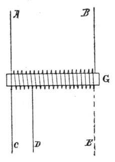
It will be observed in the diagram (Fig. 11), that the lights are taken off of either circuit, between which there is a difference of potential at this point of about 220 volts. The lamps require but 110 volts. The usual method would require either that the lamps should be wired two in series or that the potential be reduced by means of a transformer. Instead of the usual transformer with separate primary and secondary windings, the balancing coil is here used. While the functions of this coil are doubtless well understood by many of the readers of this paper, it may be well for the benefit of others to describe it in detail. In Fig. 11 this coil is represented by E, and in Fig. 12 on a larger scale by G. In the latter figure, A and B are the two sides of the 220 volt circuit connected to the terminals of a coil with iron core G. If there were no secondary coil, or if the secondary coil were open, this coil would act by self-induction as a choking coil, and no current could pass from A to B. For the purposes of illustration I have represented this coil as having twenty complete turns. If to one end the wire C were attached, and another one D were attached to the fifth turn, then the twenty turns would act as a primary and the five as a secondary — the currents in the two being in opposite phase, and the reduction of potential between these two wires would be from 220 volts to 55. If now a third wire E were attached to the other end of the coil, the whole coil would again act as a primary to that portion of the coil between D and E as a secondary — in this case fifteen turns — and the potential between these two wires would be 15/20 of the primary voltage, or 165 volts. By this means it is possible with a single coil to divide up the voltage into two or more parts by including between the secondary wires the proper proportions of the coils to effect the desired reduction. It is in fact a transformer, but one of exceedingly simple and economical construction, and for distributing a 220 volt current to 110 volt lamps is made use of by connecting a neutral wire into the center of the coil, and from this elementary three-wire circuit taking off the two-wire circuits at convenient points. Since the coil is equally divided between the two circuits, the electromotive force of the primary is also equally divided between the two branches, and there is obtained 110 volts in each branch. If it were desired to take off four circuits of 55 volts each, for arc lamps or other purposes, the coil would be divided into four equal portions, or any other portion of the primary voltage could be obtained in the secondary by simply including between the two wires of the secondary the proper proportion of the primary coils.
The advantage of this arrangement over the two-coil transformer for this purpose is its simplicity and the economy both of copper and of attendant copper losses.
TWO-PHASED MOTORS.
The motors' currents are taken off the two circuits as shown in Fig. 11, the connections being made as shown at M. The alternating current motor is in reality a transformer so constructed as to permit of relative motion between the primary and secondary coils. If either one of these be fixed in position, the other becomes the rotating part, and from one point of view it is entirely immaterial which is made the stationary and which the rotating part. Carelessness in the use of language has accustomed us to refer to the rotating member of a motor as the armature, but strict scientific accuracy forbids such indiscriminate use of the term. The Westinghouse Company are therefore to be commended for introducing a more accurate nomenclature, which is bound to find general acceptance as soon as it is better known. At the Westinghouse Works the word "armature" is no longer used when speaking of the two-phased motor, but it is described as the "rotating primary" or rotating secondary" as the impressed E. M. F.'s are led into the rotating or the stationary part. There is nothing in direct current practice to indicate the advisability of introducing resistances into the armature circuit, and they are avoided as far as possible except for starting purposes, when their function is simply prevent too great a rush of current. These resistances are not only wasteful, but actually cut down the starting torque of the motor by the exact amount by which they cut down the current. The starting resistance in a direct current motor is therefore the lesser of two evils, because nothing could be worse for the motor than to have its armature burn out, as it most surely would do if started under heavy load without the resistance. It has been found, however, that in the polyphase motor the starting resistance has performed a valuable service, viz., it increases the starting torque of the motor.
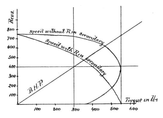
For the purpose of illustration the diagram, Fig. 13, is given. These curves are not intended to be correct, but merely to illustrate the point which it is desired to emphasize. If a polyphase motor were started without a resistance in its secondary, the curve determined by torque and speed would be something like the upper one. The torque would be comparatively low at start, but reach a maximum in this case when the speed had reached 400 revolutions per minute.
Now the torque of that particular motor can never exceed this maximum, but the position of the maximum may be made to come anywhere on the vertical line passing through this point desired and will descend as the resistance in the secondary increases. If this resistance be just right, the point will be brought down to the intersection of this vertical line with the line of no speed, or in other words, the motor will have its maximum torque at starting. Under these conditions the curve will take the form shown in the lower of the two curves, which is an actual curve taken from a 40 H. P. 220 volt two-phase motor with old style switch.
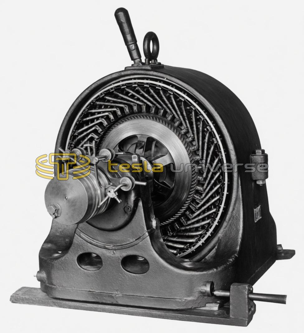
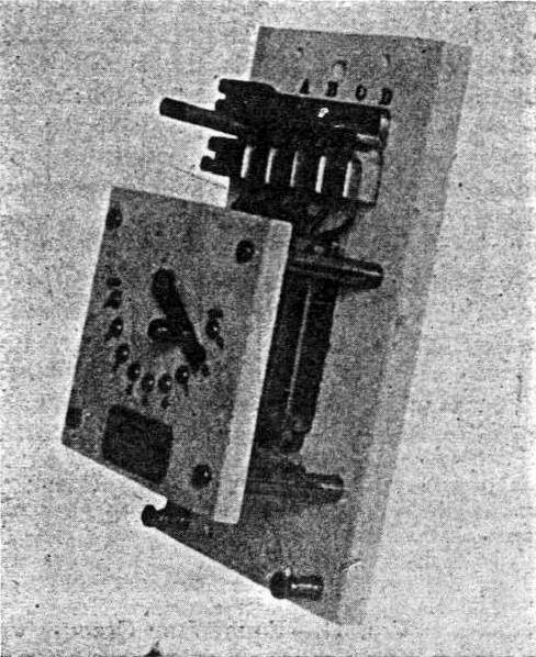
The resistance which performed this valuable function of giving the motor its maximum torque at starting in addition to preventing a too great rush of current at that time, will, after speed has been attained, be a detriment, so that means are provided by which it can be then cut out. To facilitate the cutting in and out of the starting resistances the larger sized motors which are likely to be called upon to exert a heavy starting torque are usually made with a stationary secondary — the current from the line being led to the revolving part by means of brushes bearing upon four rings on the shaft. Fig. 3 represents a motor of this kind. In this the brushes are of an improved type, but the switch is one that, although still used, is being superseded by another to be described later. In the old style, Fig. 3, all of the windings of the secondary are in series with each other, and when the switch is open are also in series with the starting resistances. When speed is attained these resistances are simply short-circuited by closing the switch, as shown in the engraving. The new style switch shown in Fig. 4, is considered a great improvement on this and is arranged as follows: At starting each conductor of the secondary is in series with a small resistance and with every other conductor. By means of a closed copper ring and sliding contacts connected with it, by a movement of the controlling switch, not only are the starting resistances thrown out of circuit but all of the conductors of the secondary are thrown from a series arrangement into a parallel one, being short-circuited on this ring. This not only greatly reduces the internal resistance of the secondary windings over that which is possible by the previously described arrangement, where at best they are in series, but leaves each of the short conductors free to act independently irrespective of the disturbing influences which the others might have upon it were they all in series. In Fig. 4 the brushes are of the old style. No photograph has yet been taken of the improved type motor, and it cannot therefore be shown here, but if the brushes shown in Fig. 3 were substituted for those shown in Fig. 4 the latter would then accurately represent the latest development of the Tesla two-phase motor with revolving primary.
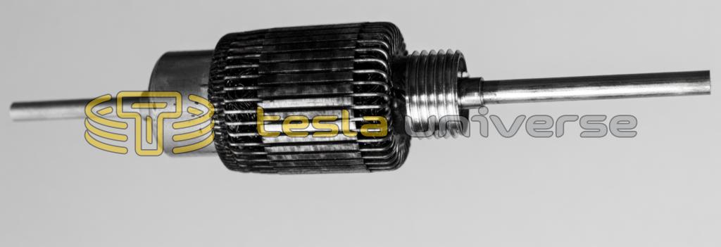
For the smaller sizes, where a starting torque is not so essential, the primary coil is made the stationary part and the secondary coil the revolving part. The primary is a continuous winding of the drum type with connections brought out to binding posts from the points 90° apart. The secondary consists of a laminated iron cylinder into whose surface are sunk copper bars of large section, forming elements of the cylindrical surface. These copper bars, which form the windings of the secondary, are simply short-circuited at both ends on heavy copper rings, as is the case in Fig. 4 when the latter has reached speed. There are no collecting rings, brushes or other means of connection between the rotating part and the outside circuit on motors of this type, and although they do not attain a maximum torque until considerable speed is reached, they still have an initial torque sufficient to start under a very considerable load.
While the two-phase motor is the only kind at present in use in these shops, the company also makes several other types, one of which, the three-phase motor, similar to those employed in the Lauffen-Frankfort experiment, is shown in Fig. 14. Another type is the single-phase syn- chronous motor, such as has been in successful use for about four years in the long mining transmission plant at Telluride, Col. This latter type will not start under load, but when brought up to a speed synchronous with the generator it will then take the load and maintain it without further attention. In this motor the fields are excited by a direct current derived from a second winding parallel with the main coils around the teeth of the armature. This is commutated and led to the field coils.
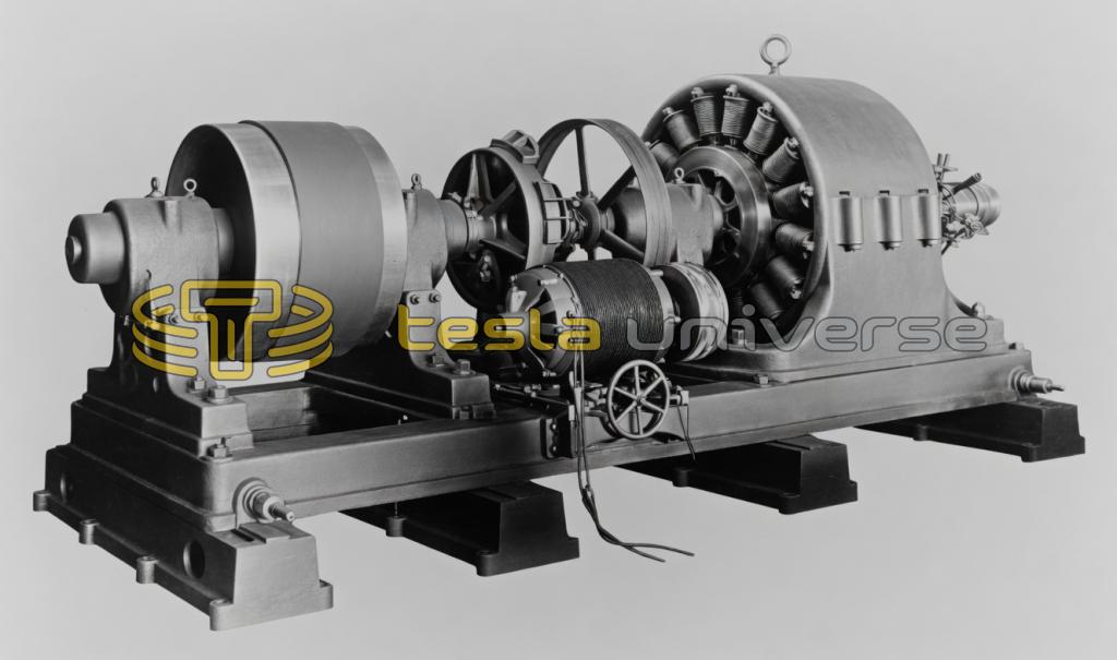
A motor of the synchronous type requires an auxiliary device for starting, however, which is usually a small motor — a special modification of the Tesla type. Fig. 15 is a photograph of a 250 H. P. synchronous motor, with the Tesla starting motor and friction clutch, installed at Telluride some years ago and still in successful operation.
With this somewhat hasty and necessarily incomplete description of the New Westinghouse Works this paper must be brought to a close. Much that would be of interest has been passed over lightly or omitted entirely, but enough has been said probably to verify the opinion expressed in the beginning, that this is the most interesting, and from many points of view the most important, electrical installation thus far attempted.