Nikola Tesla Articles
Tesla's Electrical Oscillators (Jan. 10, 1894)
Mr. Nikola Tesla, at the World's Fair Congress of Electricians, first drew attention to his method and apparatus for the continuous production of alternating currents of constant period, and in which he avoids all rotating parts by applying his oscillating engine directly to the movement of the generating coil in the magnetic field. The reason no engine heretofore has produced results of this nature is that it has been customary to connect with the reciprocating parts a heavy fly-wheel or some equivalent rotary system of relatively very great inertia, or in other cases where no rotary system was employed, as in certain reciprocating engines or tools, no regard has been paid to obtaining the conditions essential to the end which Mr. Tesla had in view. In applying the Tesla oscillator for the generation of currents of constant period, certain conditions are encountered which must be taken into consideration in order to satisfactorily secure the desired result.
When a conductor is moved in a magnetic field and a current caused to circulate therein, the electro-magnetic reaction between it and the field might disturb the mechanical oscillation to such an extent as to throw it out of isochronism. This, for instance, might occur when the electro magnetic reaction is very great in comparison to the power of the engine, and there is a retardation of the current so that the electro-magnetic reaction might have an effect similar to that which would result from a variation of the tension of the spring; but if the circuit of the generator be adjusted so that the phases of the electro-motive force and current coincide in time, that is to say, when the current is not retarded, then the generator driven by the engine acts merely as a fractional resistance and will not, as a rule, alter the period of the mechanical vibration, although it may its amplitude. This condition may be readily secured by properly proportioning the self-induction and capacity of the circuit including the generator. Mr. Tesla has, however, observed the further fact in connection with the use of such engines as a means for running a generator, that it is advantageous that the period of the engine and the natural period of electrical vibration of the generator should be the same, as in such case the best conditions for electrical resonance are established, and the possibility of disturbing the period of mechanical vibrations is reduced to a minimum.

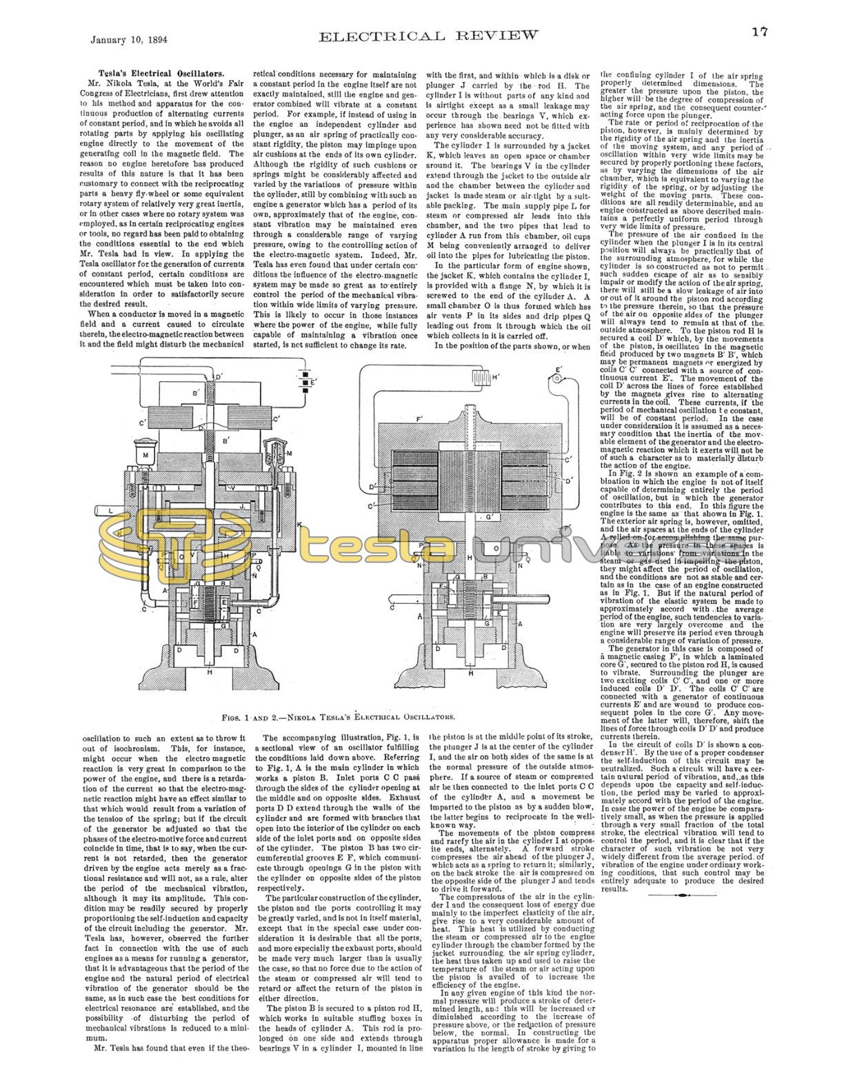
FIGS. 1 AND 2. — NIKOLA TESLA'S ELECTRICAL OSCILLATORS.

Mr. Tesla has found that even if the theoretical conditions necessary for maintaining a constant period in the engine itself are not exactly maintained, still the engine and generator combined will vibrate at a constant period. For example, if instead of using in the engine an independent cylinder and plunger, as an air spring of practically constant rigidity, the piston may impinge upon air cushions at the ends of its own cylinder. Although the rigidity of such cushions or springs might be considerably affected and varied by the variations of pressure within the cylinder, still by combining with such an engine a generator which has a period of its own, approximately that of the engine, constant vibration may be maintained even through a considerable range of varying pressure, owing to the controlling action of the electro-magnetic system. Indeed, Mr. Tesla has even found that under certain conditions the influence of the electro-magnetic system may be made so great as to entirely control the period of the mechanical vibration within wide limits of varying pressure. This is likely to occur in those instances where the power of the engine, while fully capable of maintaining a vibration once started, is not sufficient to change its rate.
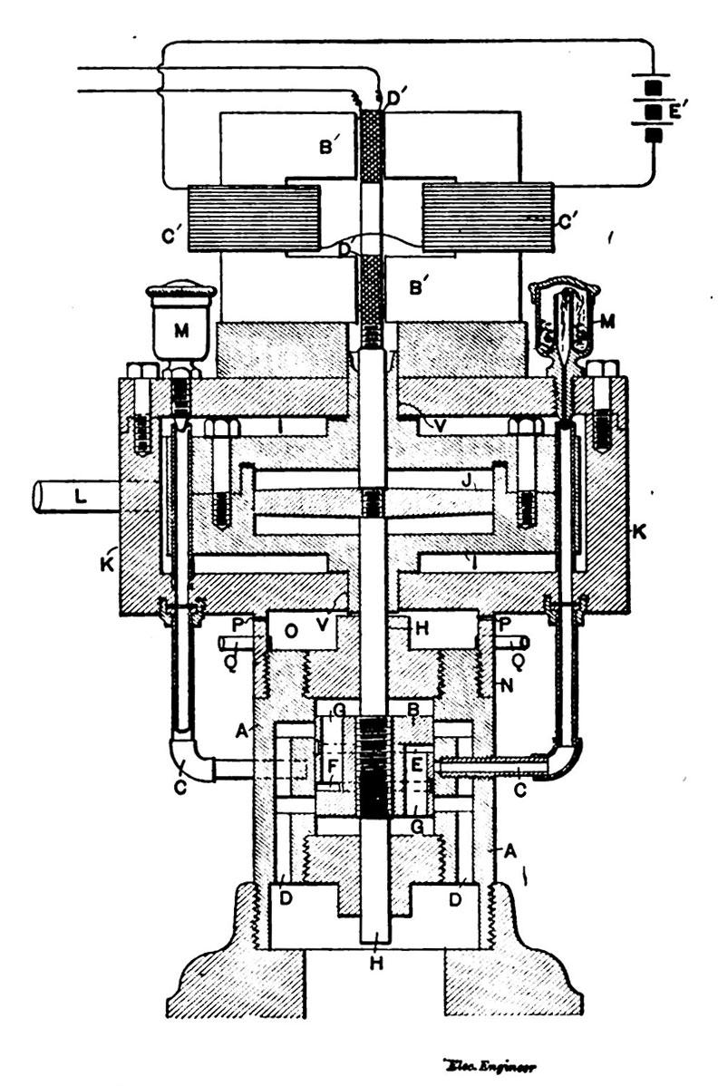
The accompanying illustration, Fig. 1, is a sectional view of an oscillator fulfilling the conditions laid down above. Referring to Fig. 1, A is the main cylinder in which works a piston B. Inlet ports C C pass through the sides of the cylinder opening at the middle and on opposite sides. Exhaust ports D D extend through the walls of the cylinder and are formed with branches that open into the interior of the cylinder on each side of the inlet ports and on opposite sides of the cylinder. The piston B has two circumferential grooves E F, which communicate through openings G in the piston with the cylinder on opposite sides of the piston respectively.
The particular construction of the cylinder, the piston and the ports controlling it may be greatly varied, and is not in itself material, except that in the special case under consideration it is desirable that all the ports, and more especially the exhaust ports, should be made very much larger than is usually the case, so that no force due to the action of the steam or compressed air will tend to retard or affect the return of the piston in either direction.
The piston B is secured to a piston rod H, which works in suitable stuffing boxes in the heads of cylinder A. This rod is prolonged on one side and extends through bearings V in a cylinder I, mounted in line with the first, and within which is a disk or plunger J carried by the rod H. The cylinder I is without parts of any kind and is airtight except as a small leakage may occur through the bearings V, which experience has shown need not be fitted with any very considerable accuracy.
The cylinder I is surrounded by a jacket K, which leaves an open space or chamber around it. The bearings V in the cylinder extend through the jacket to the outside air and the chamber between the cylinder and jacket is made steam or air-tight by a suitable packing. The main supply pipe L for steam or compressed air leads into this chamber, and the two pipes that lead to cylinder A run from this chamber, oil cups M being conveniently arranged to deliver oil into the pipes for lubricating the piston.
In the particular form of engine shown, the jacket K, which contains the cylinder I, is provided with a flange N, by which it is screwed to the end of the cylinder A. A small chamber O is thus formed which has air vents P in its sides and drip pipes Q leading out from it through which the oil which collects in it is carried off.
In the position of the parts shown, or when the piston is at the middle point of its stroke, the plunger J is at the center of the cylinder I, and the air on both sides of the same is at the normal pressure of the outside atmosphere. If a source of steam or compressed air be then connected to the inlet ports C C of the cylinder A, and a movement be imparted to the piston as by a sudden blow, the latter begins to reciprocate in the well-known way.
The movements of the piston compress and rarefy the air in the cylinder I at opposite ends, alternately. A forward stroke compresses the air ahead of the plunger J, which acts as a spring to return it; similarly, on the back stroke the air is compressed on the opposite side of the plunger J and tends to drive it forward.
The compressions of the air in the cylinder I and the consequent loss of energy due mainly to the imperfect elasticity of the air, give rise to a very considerable amount of heat. This heat is utilized by conducting the steam or compressed air to the engine cylinder through the chamber formed by the jacket surrounding the air spring cylinder, the heat thus taken up and used to raise the temperature of the steam or air acting upon the piston is availed of to increase the efficiency of the engine.
In any given engine of this kind the normal pressure will produce a stroke of determined length, and this will be increased or diminished according to the increase of pressure above, or the reduction of pressure below, the normal. In constructing the apparatus proper allowance is made for a variation in the length of stroke by giving to the confining cylinder I of the air spring properly determined dimensions. The greater the pressure upon the piston, the higher will be the degree of compression of the air spring, and the consequent counteracting force upon the plunger.
The rate or period of reciprocation of the piston, however, is mainly determined by the rigidity of the air spring and the inertia of the moving system, and any period of oscillation within very wide limits may be secured by properly portioning these factors, as by varying the dimensions of the air chamber, which is equivalent to varying the rigidity of the spring, or by adjusting the weight of the moving parts. These conditions are all readily determinable, and an engine constructed as above described maintains a perfectly uniform period through very wide limits of pressure.
The pressure of the air confined in the cylinder when the plunger J is in its central position will always be practically that of the surrounding atmosphere, for while the cylinder is so constructed as not to permit such sudden escape of air as to sensibly impair or modify the action of the air spring, there will still be a slow leakage of air into or out of it around the piston rod according to the pressure therein, so that the pressure of the air on opposite sides of the plunger will always tend to remain at that of the outside atmosphere. To the piston rod H is secured a coil D' which, by the movements of the piston, is oscillated in the magnetic field produced by two magnets B' B', which may be permanent magnets or energized by coils C' C' connected with a source of continuous current E'. The movement of the coil D' across the lines of force established by the magnets gives rise to alternating currents in the coil. These currents, if the period of mechanical oscillation be constant, will be of constant period. In the case under consideration it is assumed as a necessary condition that the inertia of the movable element of the generator and the electromagnetic reaction which it exerts will not be of such a character as to materially disturb the action of the engine.
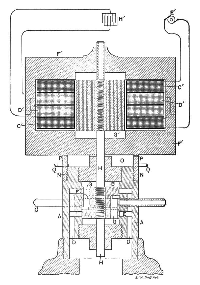
In Fig. 2 is shown an example of a combination in which the engine is not of itself capable of determining entirely the period of oscillation, but in which the generator contributes to this end. In this figure the engine is the same as that shown in Fig. 1. The exterior air spring is, however, omitted, and the air spaces at the ends of the cylinder A relied on for accomplishing the same purpose. As the pressure in these spaces is liable to variations from variations in the steam or gas used in impelling the piston, they might affect the period of oscillation, and the conditions are not as stable and certain as in the case of an engine constructed as in Fig. 1. But if the natural period of vibration of the elastic system be made to approximately accord with the average period of the engine, such tendencies to variation are very largely overcome and the engine will preserve its period even through a considerable range of variation of pressure.
The generator in this case is composed of a magnetic casing F', in which a laminated core G', secured to the piston rod H, is caused to vibrate. Surrounding the plunger are two exciting coils C' C', and one or more induced coils D' D'. The coils C' C' are connected with a generator of continuous currents E' and are wound to produce consequent poles in the core G'. Any movement of the latter will, therefore, shift the lines of force through coils D' D' and produce currents therein.
In the circuit of coils D' is shown a condenser H'. By the use of a proper condenser the self-induction of this circuit may be neutralized. Such a circuit will have a certain natural period of vibration, and, as this depends upon the capacity and self-induction, the period may be varied to approximately accord with the period of the engine. In case the power of the engine be comparatively small, as when the pressure is applied through a very small fraction of the total stroke, the electrical vibration will tend to control the period, and it is clear that if the character of such vibration be not very widely different from the average period of vibration of the engine under ordinary working conditions, that such control may be entirely adequate to produce the desired results.