Nikola Tesla Books
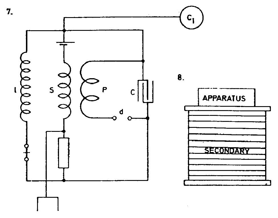
of winding secondary and primary on a large drum (8.) serving at the same time as table is best. Tuning is easy, apparatus cheap, a large amount of copper may be easily placed in the synchronized circuit.
Colorado Springs
Aug. 15, 1899
Change of secondary of oscillator to adapt it to the jars.
Capacity for one tank 36 bottles 0.03816 mfd. Two sets of tanks, 8 in each, give in series a total capacity of 4 tanks that is 0.15264 mfd.
From this !$ {T = {2.054 \over 10^{5}}} !$ approx, and n = 48,700 or nearly 49,000.
This gives λ = 3.8 miles, or for !$ {λ \over 4} !$ = 5016 feet.
Now resonance of present secondary 5280 feet was obtained with total capacity of 6 tanks instead of 4. Reducing the figures for length we should have for smaller length a capacity larger in proportion !$ {\left(5280 \over 5016\right)^{2}} !$, or 1.11 that is instead of 4 tanks we should have had 4.44 for 5280 feet.
The required length for 6 tanks capacity. This length would be
!$ {{{\sqrt{{4.44 \over 6}}} \times 5280} = {{2.17 \over 2.45} \times 5280} = 4677} !$ feet.
5280 present length4677 required " } to take off 603 feet.
With this length the oscillator will require same capacity as extra coil and good results may be expected.
152
August 15-21
With the new condenser bank the secondary had to be modified, and on August 15th he worked out the length of wire required. He calculated the period of the primary from the capacity of the new bottles and the inductance per turn of the primary found earlier (mentioned on June 20th as 7 x 104 cm, probably one quarter of the value measured for two turns on June 17th). It was also his intention to adjust the oscillator to the "extra coil".
The entries for 16, 17, 20 and 21 August give some new circuit diagrams for the oscillator which he thought would be more suitable for working at high excitation voltages. They bear witness to Tesla's constant search for improvements involving only limited changes in the apparatus which he used for lower voltages. The chief problem was overloading of the power supply. It is recorded elsewhere that Tesla's experiments with his spark oscillator (probably on some other occasion) burnt out the generator of a power station five miles away(36).
August 15-26
In order to adjust the oscillator secondary to the new capacitor battery, on August 15 he calculates the wire length for a modified secondary. The primary period he calculates on the basis of the new capacitance of the jar and previously defined inductance of one primary turn (the value of this inductance 7 x 104cm appears on June 20, and that is probably one quarter of the measured value found for two turns in series on June 17. He made the calculation with the intention to adjust the oscillator circuits with "additional coil".
On Aug. 16 and 17, he considers a new connection of the supply transformer with a centre tap. The experiment goal is the achievement of larger spark interruptions in the arcing device, the reduction of the influence of spark resistance and better use of the supply transformer. In order to reduce the network transformer secondary winding short-circuit, he plans the use of two inductive coils (please see schematic of August 17).
On August 18, he performs the approximate calculation of an oscillation period by connecting capacitor batteries in series. This should enable operation of supply voltages up to 45 kv. The change of the oscillation period due to secondary influence he estimates very approximately. He assumes that the secondary with reduced number of turns (29 instead of previous 36½), estimating that the link will be weaker than previously, and therefore the reduction of the primary inductance will be percentage-wise smaller (please see July 9).
On August 19, he performs the experiments with the oscillator and comes to the important information that with a network transformer voltage increase changes in oscillator operation will occur. At 22.5 kv this overload occurred as well as a voltage drop on primary side of the network transformer*. With the same oscillator on 15 kv the network voltage did even increase. Later on he increased the primary (which he easily achieved by connecting two available primary turns), reduced the capacitance in the primary and achieved reliable operation at high voltage.
On August 20, he continues the experiments with the oscillator which has 29 turns in the secondary. The excitation voltage is increased to 30 kv and he uses four capacitor groups connected in series. It was observed that with the bulbs lit brightest on the supply side, there were no sparks jumping on the arcing device. He concluded that at the time the minimum electro-motive force is on the secondary side of the Westinghouse transformer. Tesla doesn't comment on this unusual conclusion which at first glance appears to be unbelievable. (This could be explained because he was too busy with other problems).
The attempt of arcing device location change didn't give the expected improvement.
On August 21, he experiments with three oscillator connection schemes with the double number of sparks on the arcing device, but except for some small improvements, doesn't achieve acceptable results. The main difficulties were secondary overloading of the network transformer and the restriction of oscillator maximum power.
For one day he discontinued writing about experiments (August 22) with transmitters and he worked again with receivers. A test of two receiver schematics with one battery and one sensitive device. The capacitance in the primary circuit, he was changing within wide limits and why one microfarad is the best, is not completely clear.
The open question remains what is the relation between the frequency of the incoming signal and the signal that is generated by receiver. Maybe there is a possibility of signal amplification, similarly as with the heterodyne receiver(55), because the rotating coherer (sensitive device) behaves as a non-linear element?
On Aug. 23, Tesla returns again to experiments with the oscillator. New ''additional coil" is put in the middle of the primary coil. Already the first experiment successfully demonstrates the efficiency and power of the oscillator. After connecting the secondary with "additional coil" (for which he considers they have the same resonant frequencies) he stopped the experiment as soon as the fire danger appeared. After positioning the grounded metal globe in the vicinity of the globe at the top of the "additional coil", the security increased. He easily achieved sparks from the coil top towards a grounded globe at a distance of more than two meters.
According to estimates, Tesla expected that with one turn in primary oscillator operates at half of the frequency compared with the secondary "additional coil" resonant frequency. That's why he performed the experiment with two primary turns in series, but the result disappointed him. He left further experiments on harmonics and returned to a scheme with which he had previously achieved good results. Now he achieved sparks of more than four meters in length, fast, explosive and very white. It appears that the capacitance adjustment in the primary was not critical. The current streamers wandered around and they could be observed at a certain distance from the oscillator (as e.g., the sparks from water pipes!)
Next day as well (August 24) he continued his successful experiments. By studying the occurrence of current lines, he concluded that it is necessary to use either faster or synchronous arcing breaker. Current streamers he created so that he removed metal globe from the additional coil top and positioned a bare copper wire around the upper edge of the coil.
On Aug. 25, he performs various experiments with "additional coil". He puts the open loops in the vicinity of upper end lower portion of the coil. He observed that the current streamers have a tendency to channel upwards and beside the grounded lower conductor.
On Aug. 26, he experiments with two times higher interruptions of rotating breaker-arcing device. Oscillator operation improved, and very intensive sparking appeared on the lightning protector (Fig. 4). When studying the cause for this sparking, Tesla inserts the coil in a metal globe conductor (Fig. 1) with the intention of preventing the appearance of currents of high frequency. Once earlier (see July 30), he managed to perform an experiment where the insertion of a coil in the grounding conductor of globe stopped the sparking on lightning protector or ground. Now that hasn't been achieved and therefore Tesla tests the scheme in Fig. 2, and since there was no change, the sparking on lightning protector or lightning ground was only reduced slightly. After this experiment Tesla begins to think that the location of a maximum is the grounding of the secondary, and not the node point of the standing wave. In order to understand this, it is necessary to recall that Tesla assumed that standing or non-moving wave exists around the transmitter (as on the open line). At shorter waves, the change along the ground would be fast (it has maximums and minimums which would be repeated at a shorter distance from the transmitter than at long waves), and therefore Tesla thought that at a short distance between oscillator secondary grounding and grounding of lightning protector, a large potential difference could be achieved.
In order to explain what happens when globe grounding doesn't exist (when, therefore, there is no short wave production) since the sparking on lightning protector doesn't stop, Tesla established a new hypothesis. It is possible to produce the sparks by means of static induction to the wire through the air, and not, mainly, by conduction through the ground?" The experiment by which he attempts to prove this hypothesis didn't provide a definite answer.
* Tesla mentioned the increase in electromotive force as well as oscillator operation when he eliminated the network overloading. He didn't explain where he measured this increase or drop, but it could be said that he concluded this on the basis of bulk light intensity estimate. Bulbs were, probably, on low voltage and therefore he concluded that the voltage change was measured on the primary side of the supply transformer.


