Nikola Tesla Books
Colorado Springs
Sept. 25, 1899
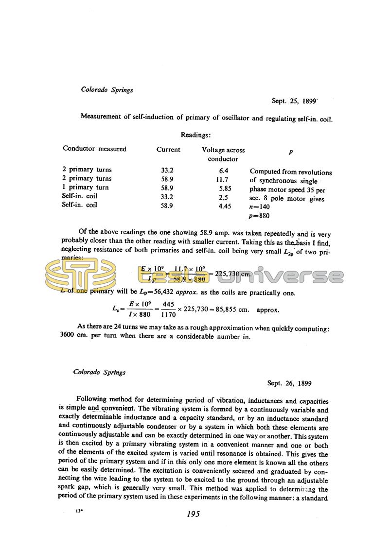
Measurement of self-induction of primary of oscillator and regulating self-in. coil.
Readings:
| Conductor measured | Current | Voltage across conductor | p |
|---|---|---|---|
| 2 primary turns | 33.2 | 6.4 | Computed from revolutions of synchronous single phase motor speed 35 per sec. 8 pole motor gives n=140 p=880 |
| 2 primary turns | 58.9 | 11.7 | |
| 1 primary turn | 58.9 | 5.85 | |
| Self-in. coil | 33.2 | 2.5 | |
| Self-in. coil | 58.9 | 4.45 |
Of the above readings the one showing 58.9 amp. was taken repeatedly and is very probably closer than the other reading with smaller current. Taking this as the basis I find, neglecting resistance of both primaries and self-in. coil being very small L2p of two primaries:
!$ {{{E \times 10^{9}} \over l p} = {{11.7 \times 10^{9}} \over {58.9 \times 880}}} !$ = 225,730 cm.
L of one primary will be Lp = 56,432 approx. as the coils are practically one.
!$ {L_{c} = {{E \times 10^{9}} \over {I \times 880}} = {445 \over 1170}} !$ = 85,855 cm. approx.
As there are 24 turns we may take as a rough approximation when quickly computing: 3600 cm. per turn when there are a considerable number in.
Colorado Springs
Sept. 26, 1899
Following method for determining period of vibration, inductances and capacities is simple and convenient. The vibrating system is formed by a continuously variable and exactly determinable inductance and a capacity standard, or by an inductance standard and continuously adjustable condenser or by a system in which both these elements are continuously adjustable and can be exactly determined in one way or another. This system is then excited by a primary vibrating system in a convenient manner and one or both of the elements of the excited system is varied until resonance is obtained. This gives the period of the primary system and if in this only one more element is known all the others can be easily determined. The excitation is conveniently secured and graduated by connecting the wire leading to the system to be excited to the ground through an adjustable spark gap, which is generally very small. This method was applied to determining the period of the primary system used in these experiments in the following manner: a standard
13*
195
Tesla N. "System of transmission of electrical energy", U.S. Patent 645 576, March 20, 1900, Appl. Sept. 2, 1897.
September 25
As he often did earlier, before finalizing a set up Tesla measured the inductance of the primary and the regulation coil which he usually used as an added, adjustable primary inductance. The value he obtained for L2p differs from that obtained earlier (see July 17th) by the same method.
September 25
He measures the inductance of the primary and the regulating coil, which serves as additional variable inductance in the primary circuit. The values he gets for L2p differ from the previous found ones (please see July 17) but the method is the same.
September 26
By this method the frequency of an oscillator is found with a help of a resonant circuit of known parameters. When its resonant frequency is adjusted to coincide with the frequency of the oscillator, the voltage across its terminals, estimated by the strength of the spark across an "analyzing gap", is a maximum. Tesla says that the excitation must be "convenient". Since he introduced regulation of the excitation by means of the small gap b, it is clear that "convenient" excitation was obtained with loose coupling. Loose coupling between the primary and secondary circuits of a spark oscillator ensures that the two frequencies which such an oscillator normally produces are very close. Up to a certain degree of coupling, Tesla's oscillator produces a single frequency. According to Fleming and Dyke(31), with an ordinary spark gap the maximum coupling coefficient for monochromatic oscillation is around 0.05 (certainly less than 0.1), while with a rotary break producing pulse excitation a coefficient of up to 0.2 gives good results. With higher coupling coefficients three components are obtained, even if the primary and secondary circuits by themselves have the same resonant frequency.
September 26
He shows the method to determine the oscillator frequency by means of a linked oscillator circuit of known parameters. When at a certain excitation this linked circuit is adjusted so as to have the same resonant frequency as the oscillator maximum voltage appears at the circuit terminals which is based on spark intensity analysis. Tesla mentions that the excitation has to be "convenient". Based on the fact that he introduced the excitation regulation via a small gap designated by b, it is clear that the "convenient" link has to be a weak link. A weak link between the primary and secondary circuit with arcing oscillators insures that the two frequencies, which this system normally has to produce, will be very close or equal*. If ere Tesla does not give any data on the accuracy method but judging by the conclusion that the excited circuit frequency is somewhat lower than the primary circuit frequency, by approximately 0.4%, it is likely that he assumes a high accuracy.
* For a certain link the actual Tesla oscillator produces a current of one frequency. According to Fleming and Dyke(31), with common arc devices maximum link coefficient for monochromatic operation is somewhat at approximately 0.05 (for sure less than 0.1) and with rotating arcing devices, which suddenly excites the system, even 0.2 gives good results. Stronger links in both cases cause the occurrence of free components and then particularly when primary and secondary circuits are adjusted to the same frequency.

