Nikola Tesla Books
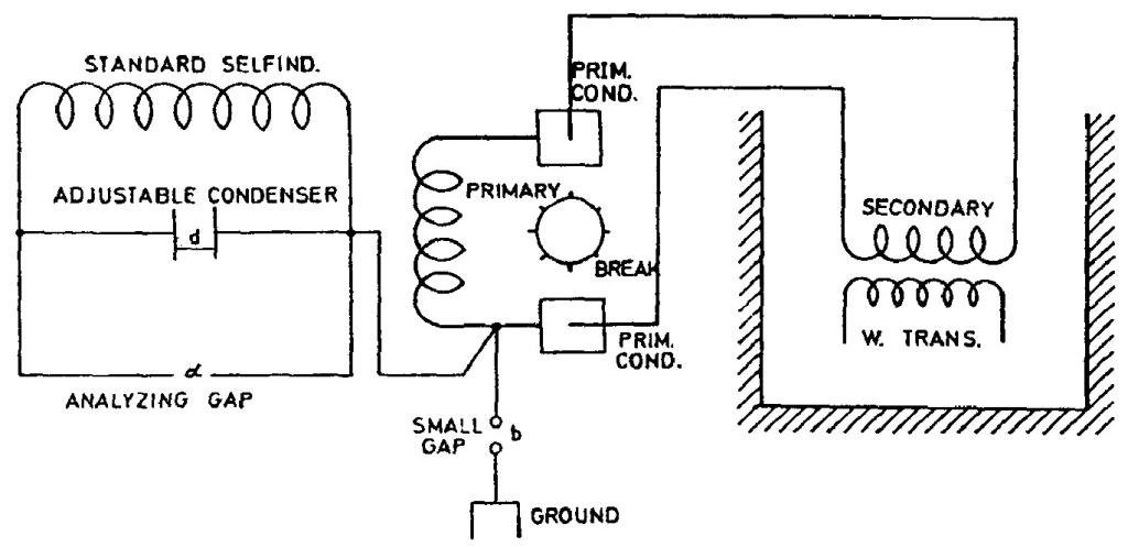
self-induction coil made long ago and used in experiments in N.Y. about 1560 turns wound on a drum 3 1/2" diam. was shunted by the adjustable condenser, also frequently used and consisting of two brass plates 20" diam., and this system was connected to one of the terminals of the Westinghouse transformer as illustrated in diagram below. By varying the length of spark at b the degree of excitation was varied to any value desired, the spark at a serving to determine maximum rise of potential on terminals of excited system.
Particulars: L = 0.0176 H. Res. of coil = 59.457 ohms, drum 3 1/2", turns 1560 approx.
| Readings in one case: | |
|---|---|
| Capacity in primary total | Inductance primary |
| 144 bottles = 0,1526 mfd. | 0.000025 H |
Tapprox = !$ {{{2 \pi \over 10^{3}} \sqrt{{0.000025 \times 0.1526}}} = {1225 \over 10^{8}}} !$
Resonance was obtained with the plates nearly 0.8 cm. apart, the period of excited system being slightly slower.
Csec = !$ {{A \over 4 \pi d} = {2027 \over {4 \pi \times 0.8}}} !$ = approx. 200 cm.
Ts approx. = !$ {1230 \over 10^{8}} !$
Colorado Springs
Sept. 27, 1899
Determination of inductance of coil used in series with extra coil when no ball was used on latter, with old secondary.
160 turns No. 10 B. & S. wire rubber-covered Habirshaw, drum 2 feet diam. 60.96 cm. Length = 42.5" = 107.95 cm.
First measurement average of readings:
I = 5.9 E = 38.25 R = 1.054 Ï = 880
!$ {{E \over I} = 6.483 = {\sqrt{(1.054)^{2} + (880 L)^{2}}}} !$
196
September 26
By this method the frequency of an oscillator is found with a help of a resonant circuit of known parameters. When its resonant frequency is adjusted to coincide with the frequency of the oscillator, the voltage across its terminals, estimated by the strength of the spark across an "analyzing gap", is a maximum. Tesla says that the excitation must be "convenient". Since he introduced regulation of the excitation by means of the small gap b, it is clear that "convenient" excitation was obtained with loose coupling. Loose coupling between the primary and secondary circuits of a spark oscillator ensures that the two frequencies which such an oscillator normally produces are very close. Up to a certain degree of coupling, Tesla's oscillator produces a single frequency. According to Fleming and Dyke(31), with an ordinary spark gap the maximum coupling coefficient for monochromatic oscillation is around 0.05 (certainly less than 0.1), while with a rotary break producing pulse excitation a coefficient of up to 0.2 gives good results. With higher coupling coefficients three components are obtained, even if the primary and secondary circuits by themselves have the same resonant frequency.
September 26
He shows the method to determine the oscillator frequency by means of a linked oscillator circuit of known parameters. When at a certain excitation this linked circuit is adjusted so as to have the same resonant frequency as the oscillator maximum voltage appears at the circuit terminals which is based on spark intensity analysis. Tesla mentions that the excitation has to be "convenient". Based on the fact that he introduced the excitation regulation via a small gap designated by b, it is clear that the "convenient" link has to be a weak link. A weak link between the primary and secondary circuit with arcing oscillators insures that the two frequencies, which this system normally has to produce, will be very close or equal*. If ere Tesla does not give any data on the accuracy method but judging by the conclusion that the excited circuit frequency is somewhat lower than the primary circuit frequency, by approximately 0.4%, it is likely that he assumes a high accuracy.
* For a certain link the actual Tesla oscillator produces a current of one frequency. According to Fleming and Dyke(31), with common arc devices maximum link coefficient for monochromatic operation is somewhat at approximately 0.05 (for sure less than 0.1) and with rotating arcing devices, which suddenly excites the system, even 0.2 gives good results. Stronger links in both cases cause the occurrence of free components and then particularly when primary and secondary circuits are adjusted to the same frequency.
September 27
He measures the auxiliary coil inductance by the same method he applied on Sept. 25, except now he takes into account the coil resistance as well (measured probably by DC current so that skirt effect was not taken into account). By following the principle that measured values have to be proven by calculation, he calculates the inductances of the same coil by means of the equation for a long coil and he does not get the expected results. In a short review of not expected results he mentioned the possibility that the distributed coil capacitance influenced the measured value. But this is difficult to believe because the distributed capacitances increase the effective inductance in frequency range below the coil self resonant frequency. Another possibility remains which Tesla mentions (the non-accuracy of coil dimensions) and low accuracy of the theoretical equation which is approximate and the ratio of the coil's length to its diameter which is very high.


