Nikola Tesla Books
!$ {L = {{\sqrt{6.483^{2} - 1.054^{2}}} \over 880} = {6.4 \over 880} =} !$ 0.00728 H or 7,280,000 cm.
Second measurement average of readings:
I = 6.77 E = 43.25 R = 1.054 Ï = 880
E = 6.39 from this L = 0.00716 H or 7,160,000 cm.
This variation probably due to change in Ï and it is probably safest to take average
{0.007160.00728} or 0.00722 H7,220,000 cm.} as best
values.
The calculated value from above dimensions is:
!$ {L = {{4 \pi N^{2} S} \over l} = {{4 \pi \times 25,600 \times 2919} \over 107.95}} !$ 8,700,000 cm. or 0.0087 henry
N2 = 25,600
!$ {S = {{\pi \over 4} 60.96^{2}} =} !$ 2919 cm. sq.
The difference must be due to the internal capacity of the coil or possibly inexactness of the dimensions above.
Colorado Springs
Sept. 28, 1899
One of the difficulties in telegraphy and a drawback in practical introduction is the elevated terminal of capacity as proposed by me. It is difficult to elevate a structure to the desired height and keep the same insulated from the ground and with very powerful vibrations, as here produced even an insulated wire leading up offers difficulties because of streamers which reduce the force and the effect at a distance.
I propose to overcome this by the following plan. A structure is to be elevated from the ground up to the desired height and an insulated wire from the oscillator is to be brought
197
September 27
He measures the auxiliary coil inductance by the same method he applied on Sept. 25, except now he takes into account the coil resistance as well (measured probably by DC current so that skirt effect was not taken into account). By following the principle that measured values have to be proven by calculation, he calculates the inductances of the same coil by means of the equation for a long coil and he does not get the expected results. In a short review of not expected results he mentioned the possibility that the distributed coil capacitance influenced the measured value. But this is difficult to believe because the distributed capacitances increase the effective inductance in frequency range below the coil self resonant frequency. Another possibility remains which Tesla mentions (the non-accuracy of coil dimensions) and low accuracy of the theoretical equation which is approximate and the ratio of the coil's length to its diameter which is very high.
September 28
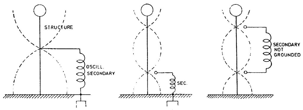
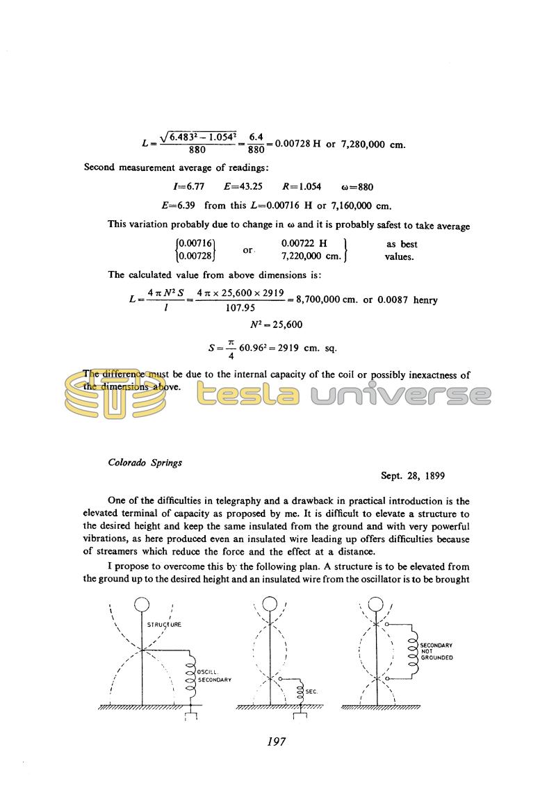
The circuit diagrams are of great interest because they illustrate a new approach to feeding the antenna (now known as shunt feed(73) which obviates the problem of insulating the aerial pole. Unfortunately the explanations Tesla gives are too cryptic to be fully comprehensible. The figures do not clearly show whether the lower terminal of the antenna is grounded or insulated. Tesla's conclusions that a standing wave is set up along the antenna and that the distance between points of equal potential is half a wavelength are correct.
The frequencies he was using were not high enough for his antennas to work in the manner shown by the figures (in which case they would be much more efficient radiators than he usually had), so that this contribution to the theory of wire antennas was never properly formulated.
September 28
Tesla displays new ideas about aerial excitation. The shown schemes are very interesting because they show a new approach to the problem of feeding the aerial (it is known today as shunt feed) by which the problem of the aerial support insulation is eliminated. Tesla's idea was that by such aerial feeding he would avoid discharge when supplying energy to the aerial. Unfortunately, the given explanations are not suficient in order to provide a clear understanding. On the figures it is not clearly designated whether the lower aerial terminal is grounded or isolated. The conclusions that the standing wave is created along the aerial and that location of the same potentials are at the distance of half a wavelength are correct. It appears that Tesla did not take into account the aerial reduction due to final capacitance when considering the events on the aerial. Remarks could be made on the chosen aerial length as well as the voltage distribution (or current?) along the aerial. Unfortunately Tesla did not apply high enough frequencies in order to get the aerials to operate under conditions as shown on the indicated figures, and so this contribution in an area of wire remains unfinished.


