Nikola Tesla Books
up to a point on the structure and connected to same or else brought into proximity, as for instance when a spark is used. This point should now be so located that there is at the same moment, say, a position maximum on top and a negative on the bottom or ground, that is the top and bottom should be one half of the wave apart or a multiple thereof.
When secondary is grounded as usual it will probably be advantageous to make the wave length in both systems so that they work in unison on the ground.
Colorado Springs
Sept. 29, 1899
Various advantageous arrangements of oscillating circuits for producing disturbances in the natural media.
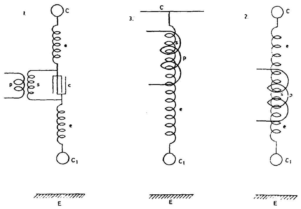
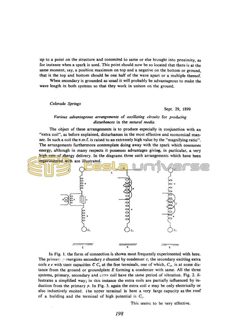
The object of these arrangements is to produce especially in conjunction with an "extra coil", as before explained, disturbances in the most effective and economical manner. In such a coil the e.m.f. is raised to an extremely high value by the "magnifying ratio". The arrangements furthermore contemplate doing away with the spark which consumes energy, although in many respects it possesses advantages giving, in particular, a very high rate of energy delivery. In the diagrams three such arrangements which have been experimented with are illustrated.
In Fig. 1. the form of connection is shown most frequently experimented with here. The primary energizes secondary s shunted by condenser c, the secondary exciting extra coils e e with their capacities C C1 at the free terminals, one of which, C1, is at some distance from the ground or groundplate E forming a condenser with same. All the three systems, primary, secondary and extra coil have the same period of vibration. Fig. 2. illustrates a simplified way; in this instance the extra coils are partially influenced by induction from the primary p. In Fig. 3. again the extra coil e may be only electrically or also inductively excited. The upper terminal is here a very large capacity as the roof of a building and the terminal of high potential is C1.
This seems to be very effective.
198
September 28
The circuit diagrams are of great interest because they illustrate a new approach to feeding the antenna (now known as shunt feed(73) which obviates the problem of insulating the aerial pole. Unfortunately the explanations Tesla gives are too cryptic to be fully comprehensible. The figures do not clearly show whether the lower terminal of the antenna is grounded or insulated. Tesla's conclusions that a standing wave is set up along the antenna and that the distance between points of equal potential is half a wavelength are correct.
The frequencies he was using were not high enough for his antennas to work in the manner shown by the figures (in which case they would be much more efficient radiators than he usually had), so that this contribution to the theory of wire antennas was never properly formulated.
September 28
Tesla displays new ideas about aerial excitation. The shown schemes are very interesting because they show a new approach to the problem of feeding the aerial (it is known today as shunt feed) by which the problem of the aerial support insulation is eliminated. Tesla's idea was that by such aerial feeding he would avoid discharge when supplying energy to the aerial. Unfortunately, the given explanations are not suficient in order to provide a clear understanding. On the figures it is not clearly designated whether the lower aerial terminal is grounded or isolated. The conclusions that the standing wave is created along the aerial and that location of the same potentials are at the distance of half a wavelength are correct. It appears that Tesla did not take into account the aerial reduction due to final capacitance when considering the events on the aerial. Remarks could be made on the chosen aerial length as well as the voltage distribution (or current?) along the aerial. Unfortunately Tesla did not apply high enough frequencies in order to get the aerials to operate under conditions as shown on the indicated figures, and so this contribution in an area of wire remains unfinished.
September 29
Tesla says that he experimented with the antennas shown in the drawings, but he does not compare them with a grounded antenna.
The shortness of the antennas relative to the wavelength made them inefficient radiators. The configuration shown in Fig. 3 was best probably because it had the greatest terminal capacity, providing the most favourable current distribution on the antenna. Lack of coil and ball dimensions makes it impossible to go into any more detailed analysis of these antennas.
September 29
Three wiring schematics are shown with final capacitances connected to isolated secondary terminals C and C1. Tesla said that he experimented with such aerials but he did not compare them with a grounded aerial. Due to their small aerial length in comparison with the wavelength, all these structures are now efficient radiators. The combination given in Fig. 3 is the best, probably because it has the largest final capacitance which provides the best current distribution along the aerial. For more detailed analysis of these aerials the data on the coils and sphere dimensions are missing.


