Nikola Tesla Books
Colorado Springs
June 9, 1899
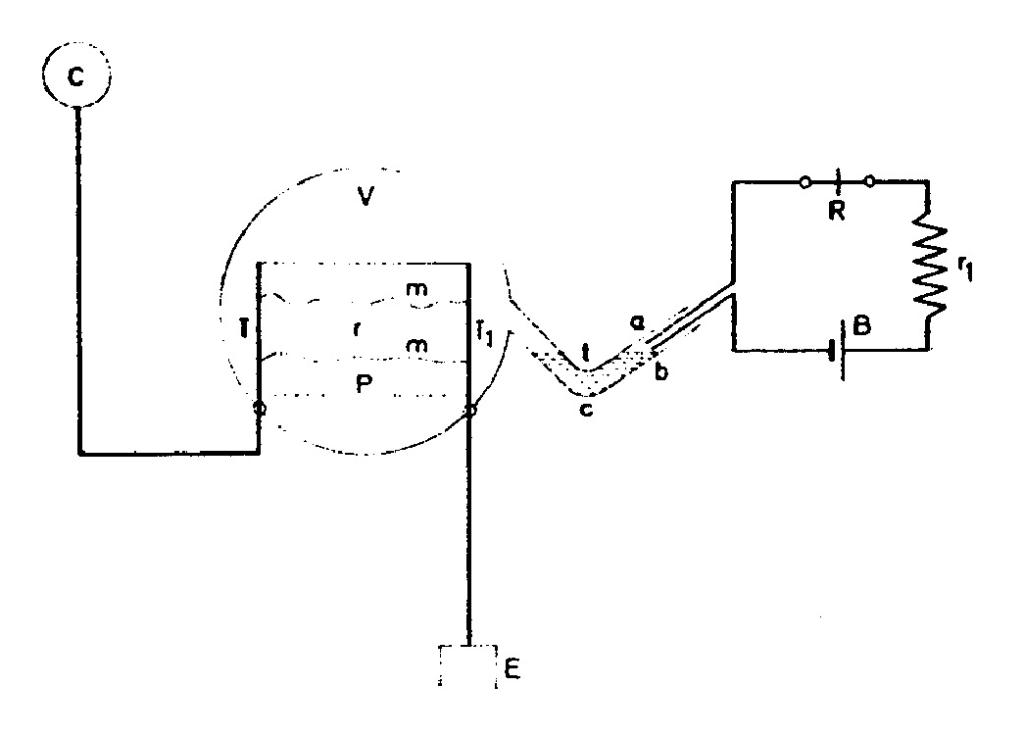
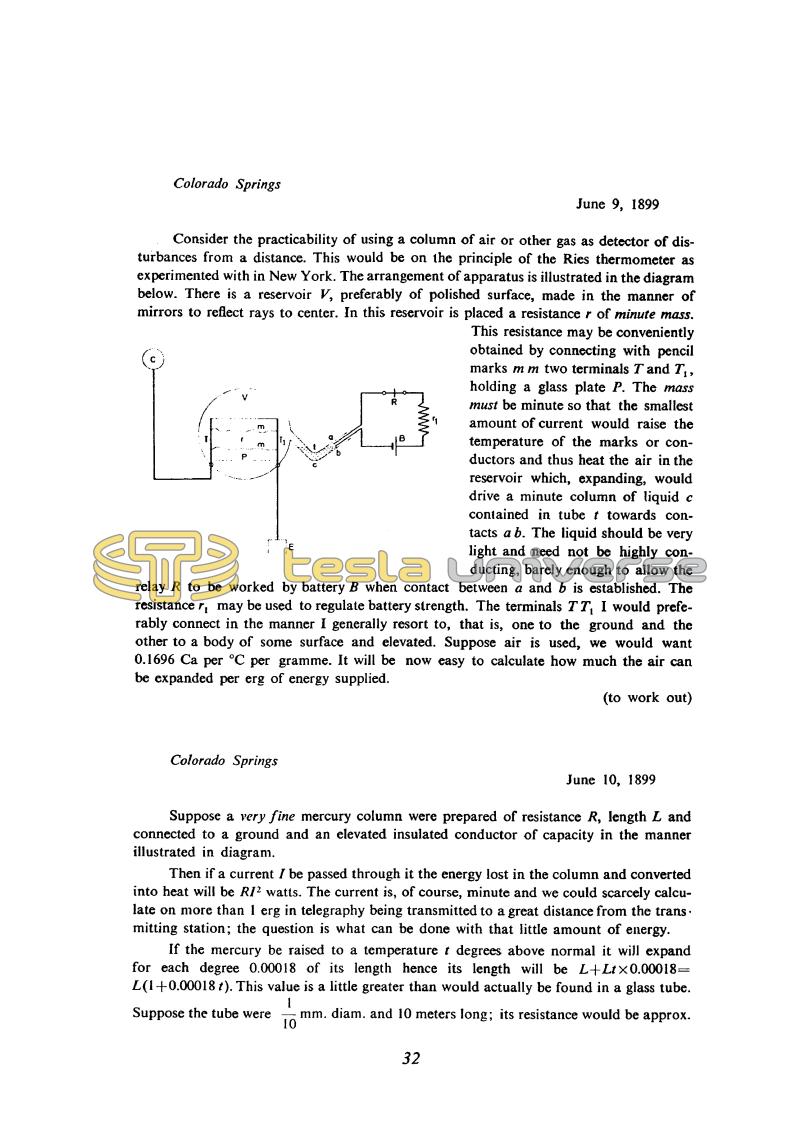
Consider the practicability of using a column of air or other gas as detector of disturbances from a distance. This would be on the principle of the Ries thermometer as experimented with in New York. The arrangement of apparatus is illustrated in the diagram below. There is a reservoir V, preferably of polished surface, made in the manner of mirrors to reflect rays to center. In this reservoir is placed a resistance r of minute mass.
This resistance may be conveniently obtained by connecting with pencil marks m m two terminals T and T1, holding a glass plate P. The mass must be minute so that the smallest amount of current would raise the temperature of the marks or conductors and thus heat the air in the reservoir which, expanding, would drive a minute column of liquid c contained in tube t towards contacts a b. The liquid should be very light and need not be highly conducting, barely enough to allow the relay R to be worked by battery B when contact between a and b is established. The resistance r1 may be used to regulate battery strength. The terminals TT1 I would preferably connect in the manner I generally resort to, that is, one to the ground and the other to a body of some surface and elevated. Suppose air is used, we would want 0.1696 Ca per °C per gramme. It will be now easy to calculate how much the air can be expanded per erg of energy supplied.
(to work out)
Colorado Springs
June 10, 1899
Suppose a very fine mercury column were prepared of resistance R, length L and connected to a ground and an elevated insulated conductor of capacity in the manner illustrated in diagram.
Then if a current l be passed through it the energy lost in the column and converted into heat will be RI2 watts. The current is, of course, minute and we could scarcely calculate on more than 1 erg in telegraphy being transmitted to a great distance from the transmitting station; the question is what can be done with that little amount of energy.
If the mercury be raised to a temperature t degrees above normal it will expand for each degree 0.00018 of its length hence its length will be L+Ltx0.00018=L(1+0.00018 t). This value is a little greater than would actually be found in a glass tube. Suppose the tube were !$ {1 \over 10} !$ mm. diam. and 10 meters long; its resistance would be approx.
32
June 9-12
In his efforts to construct a sensitive detector for small signals Tesla worked out several designs making use of the thermal effect of high-frequency current. Since the energies involved are very small (according to Tesla of the order of 1 erg), receivers based on this principle would be extremely delicate.
In the archives of the Nikola Tesla Museum, Belgrade, a slide has been found which evidences that Tesla was probably preparing to file a patent on a receiver similar to that which he described in the diary the 9th of June (see drawing on p. 399). The entry for 11th June is stamped on the back "U.S. Patent Office, Nov. 15, 1902."
The basic principle of these detectors is of an earlier date. According to Fleming(33), Gregory carried out measurements of radiation intensity by the extension of a thin wire in 1889, and Rubens and Ritter in 1890 using a bolometer.
June 9-12
Tesla develops several types of the receivers for small signals received by an antenna-ground system. Signals are registered by means of thermal effect of high frequency currents. With regards to that, it is possible to count only on small energy (according to Tesla, approximately one erg). Receivers of this type represent very delicate devices.
In the first type of receiver the resistor is of small mass, through which current flows from the antenna to the ground, heats the gas in the container with reflective walls (in order to achieve the space which doesn't exchange the heat with surrounding adiabatic space). Heated gas expansion moves the liquid drop in thin tube towards contact 'ab' (fig., June 9), and via contacts, the circuit for received signals registration is closed. In the archives of the Nikola Tesla Museum in Belgrade one slide was found (shown on p. 10) which shows that Tesla was preparing patent for the purpose of protection of receiver construction of this type. It is not known whether he submitted the patent request.
For another type of receiver (June 10), instead of small mass resistor, Tesla counts on the use of thin mercury cylinder. The received signal would be registered on the basis of mercury expansion in a thin tube. On the basis of mercury cylinder weight and necessary energy for heating one gram of mercury for one degree Celsius, he finds that required energy is considerably above the assumed signal energy. From this he concludes that the mercury cylinder would have to be much thinner.
With the receiver of the third type (June 11) High frequency current heats a small mass resistor, and signals are registered on the basis of a resistance change of this resistor. Tesla previously experimentally established that the thin carbon layer resistance is reduced during a weak signal current flow from the antenna. The resistance reduction would have to be sufficient to switch on the auxiliary relay by the action of current from the battery. In the given scheme it is expected that the system is able to receive the subsequent signals as soon as the registration of the received signal is completed. In order to increase the sensitivity Tesla foresees the use of a schematic similar to a bridge but he doesn't explain how.*
The receiver number 4 (June 12) is much more original than the previous ones. When looking for the small mass resistor, Tesla gets the idea to use thin steamed film on the plate made of insulator. The film would be formed, at suitable chosen temperatures and other conditions, in a small jar with two terminals. It is expected to form and destroy film (by means of current from battery) - probably with each received impulse.
Of the mentioned four receivers, he said (June 9 and 12) that studies have to be continued on two of them. It is interesting that those are the receivers he already worked on in the laboratory in New York.
As far as the basic principle of these considered receivers' operation is concerned the ideas are of older date. According to Fleming(33), the measurement of emission intensity on the basis of thin wire expansion, Gregory performed in 1889. Also, according to the same source, Rubens and Riter used a bolometric instrument in 1890 (a bolometer is the instrument where the amount of heat it receives is measured on the basis of its resistance range) for the purpose of the rays' emission intensity measurement.
Bolometer was made of iron wire .07mm in diameter, and the variation of its resistance was measured by means of a Wheatstone Bridge. The current was flowing through the bolometer from the antenna to ground and direct current which fed the bridge. The device was adjusted so that the antenna's current disturbs the bridge balance.
Rubens-Riter method was applied in 1904 by Tissot(33) for the purpose of electrical oscillations measurement at a long distance from the transmitter. Tissot used, instead of iron wire, a platinum wire, 10 to 20 microns thick and he detected signals at 50 km distance from the transmitter.
Tesla produced continuous high frequency currents by means of special alternators in about 1890(2) and arcing oscillators with resonant transformer starting from 1891(15). In 1893 he suggested the system for high frequency current use for the purpose of message transmission(6). Differing from other researchers in the field of radio technique who followed method suggested by Hertz(23), Tesla even in 1892, clearly recognized that it was not the way for the future of radio. Instead of dampened high frequency currents, Tesla suggested continuous currents, when the resonance can be efficiently used, which enables the selective signal reception. Instead of very short waves, where straight line radio waves propagation is emphasized, Tesla suggested the application of long waves, when the entire earth, together with the high conductive atmosphere layers, can be used for the electrical energy transmission as the "usual" conductors are in question. Continuous high frequency currents have the advantage over impulse-dampened currents that by means of them, the continuous signals can be efficiently transmitted, as for example, telephone signals. On June 13 and 14 Tesla displayed two variations of high frequency oscillators which could be used for the achievement of amplitude modulated signals. Both schemes present probably the first modulators in radio technique. It is not known whether Tesla performed experiments with such apparatus, but it is known similar ideas were materialized later on by other researchers(19).
In the scheme shown on June 13 carbon microphone 'cc' was connected in parallel to a portion of the high frequency transformer primary. Via funnel 'f' sound pressure variations vary the carbon microphone resistance, which causes the variations of oscillation intensity. Tesla's comments illustrate how much in detail he studied the idea, starting from the supply source and other practical apparatus details, to principal questions on the ratio between maximum modulated signal frequency and the carrier frequency. With regards to the latter Tesla considers that the number of primary circuit interruptions, at the location of sparking device d, has to be considerably higher than "variation" of the voice.
* On the back of Tesla's original text of June 11, 1899, there is a seal: U.S. Patent Office, Nov. 15, 1902.


